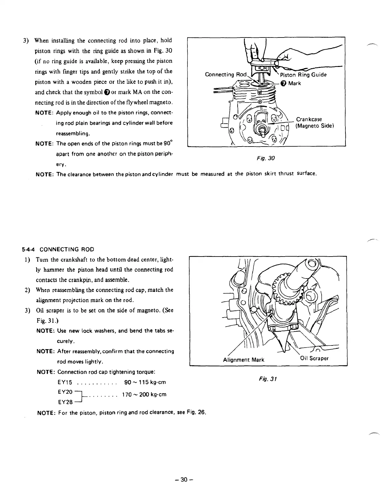
3)
When installing the connecting rod into place, hold
I
piston rings with the
ring
guide
as
shown in Fig.
30
(if
no
ring guide is available, keep pressing the piston
rings with finger tips and gently strike the top
of
the
piston with a wooden piece
or
the like
to
push
it in),
and check that the symbol
@or
mark
MA
on the con-
necting rod is in the direction
of
the flywheel magneto.
NOTE:
Apply enough oil
to
the piston rings, connect-
ing
rod
plain bearings and cylinder wall before
reassembling.
NOTE:
The open ends
of
the piston rings must be
90"
apart from one another
on
the piston periph-
Piston
Ring Guide
Fig.
30
ery
.
NOTE:
The clearance between the piston and cylinder must be measured
at
the piston skirt thrust surface.
544
CONNECTING
ROD
1)
Turn
the crankshaft to the bottom dead center, light-
ly
hammer the piston head
until
the
connecting
rod
contacts the crankpin, and assemble.
2)
When reassembhg the connecting
rod
cap, match the
alignment projection mark on the
rod.
3)
Oil scraper
is
to be set on the side
of
magneto. (See
Fig.
31
.)
NOTE:
Use new lock washers, and bend the tabs se-
curely.
NOTE:
After reassembly, confirm that the connecting
rod moves lightly.
NOTE:
Connection rod cap tightening torque:
EY15
.
,
.
.
. .
.
.
.
.
.
90-
115
kg-cm
. .
. . .
.
.
.
170
-
200
kg-cm
EY20
+-
EY28
I
Alignment
Mark
Oil
Scraper
Fig.
31
NOTE:
For the piston, piston ring and rod clearance, see Fig.
26.
-
30
-