5-4-5
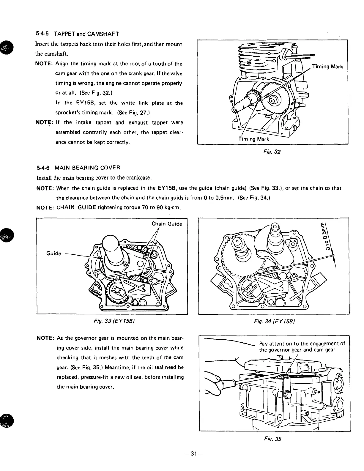
TAPPET and CAMSHAFT
Insert
the
tappets back into their holes first,
and
then
mount
the
camshaft.
NOTE:
Align the timing mark
at
the root of
a
tooth of the
cam gear with the one on the crank gear.
If
thevalve
timing
is
wrong, the engine cannot operate properly
or
at
all.
(See
Fig.
32.)
In the EY158,
set
the white link plate
at
the
sprocket’s timing mark.
(See
Fig.
27.)
NOT€:
If the intake tappet and exhaust tappet were
assembled contrarily each other, the tappet clear-
ance cannot be kept correctly.
Fig.
32
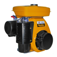
5-4-6
MAIN
BEARING COVER
Install
the
main
bearing cover
to
the
crankcase.
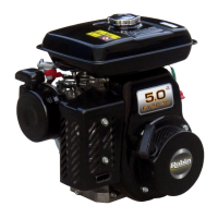
NOTE:
When the chain guide
is
replaced in the EY158, use the guide (chain guide)
(See
Fig.
33.1,
or
set
the chain
so
that
the clearance between the chain and the chain guids
is
from
0
to 0.5mm.
(See
Fig.
34.)
NOTE:
CHAIN GUIDE tightening torque
70
to
90
kgcm.
Chain Guide
n
n
Fig.
33
(E
Y
75B)
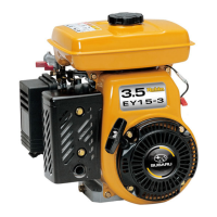
NOTE:
As
the governor gear
is
mounted on the main bear-
ing cover
side,
install the main bearing cover while
checking that
it
meshes with the teeth of the cam
gear.
{See
Fig.
35.) Meantime, if the oil
seal
need be
replaced, pressure-fit
a
new
oil
seal
before installing
the main bearing cover.
Fig.
34
(E
Y
156)
I
\
Pay attention
to
the engagement
of
the governor gear and cam gear
-
31
-