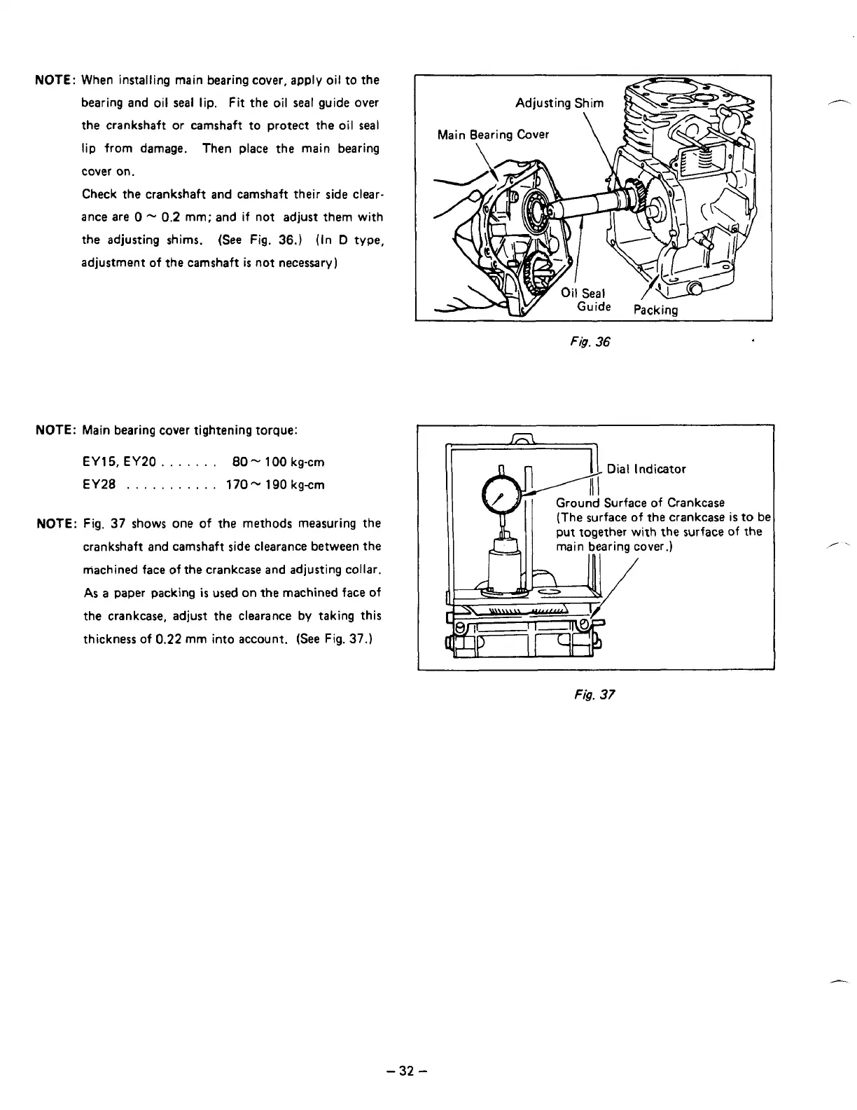
NOTE:
When installing main bearing cover, apply oil to the
bearing and oil
seal
lip.
Fit
the oil
seal
guide over
the crankshaft or camshaft to protect the oil
seal
lip from damage. Then place the main bearing
cover on.
Check the crankshaft and camshaft their side clear-
ance are
0
-
0.2
mm; and if not adjust them with
the adjusting shims. (See Fig.
36.)
(In
D
type,
adjustment of the camshaft
is
not necessary)
NOTE:
Main bearing cover tightening torque:
EY15,
EY20.
. . .
.
.
.
80-
100
kg-cm
EY28
.
.
.
.
. .
. .
.
. .
170
-
190
kgcm
NOTE:
Fig.
37
shows one
of
the methods measuring the
crankshaft and camshaft side clearance between the
machined face of the crankcase and adjusting collar.
As
a
paper packing
is
used on
the
machined face
of
the crankcase, adjust the clearance
by
taking this
thickness
of
0.22
mm into account.
(See
Fig.
37.)
Fig.
36
I
Dial Indicator
Ground Surface of Crankcase
(The surface
of
the crankcase
is
to be
II
Y=II
11
1
1
put together with the
main bearing cover.)
surface of
the
-32
-