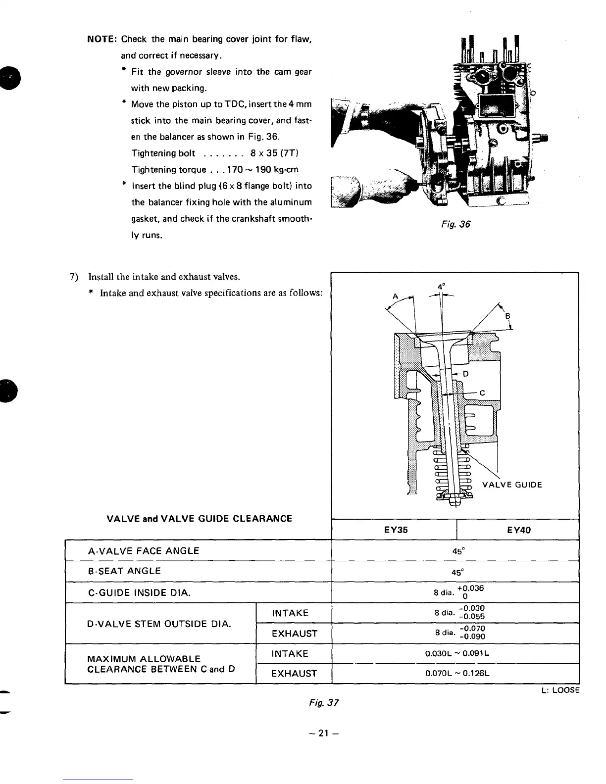
NOTE:
Check the main bearing cover joint for flaw,
and correct
if
necessary.
Fit the governor
sleeve
into
the
cam gear
with new packing.
*
Move the piston up to TDC, insert the
4
mm
stick into the main bearing cover, and fast-
en the balancer
as
shown in Fig.
36.
Tightening bolt
.
.
.
.
.
. .
8
x
35
(7T)
Tightening torque
.
.
.170
-
190
kg-cm
*
Insert the blind plug
(6
x
8
flange
bolt)
into
the balancer fixing hole with the aluminum
gasket, and check if the crankshaft srnooth-
ly
runs.
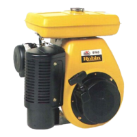
7)
Install the intake
and
exhaust valves.
*
Intake
and
exhaust valve specifications are as
follows:
VALVE
and
VALVE
GUIDE
CLEARANCE
A-VALVE FACE ANGLE
6-SEAT ANGLE
C-GUIDE INSIDE DIA.
~~~~ ~ ~
INTAKE
D-VALVE STEM OUTSIDE DIA.
MAXIMUM ALLOWABLE
CLEARANCE 8ETWEEN
C
and
D
INTAKE
Fig.
36
4O
A.4
IF
GUIDE
EY35
E
Y40
8dia.
+0.036
dia.
-0.070
-0.090
0.030L
-
0.091
L
0.070L
-
0.1
26L
Fig.
37
-21
-