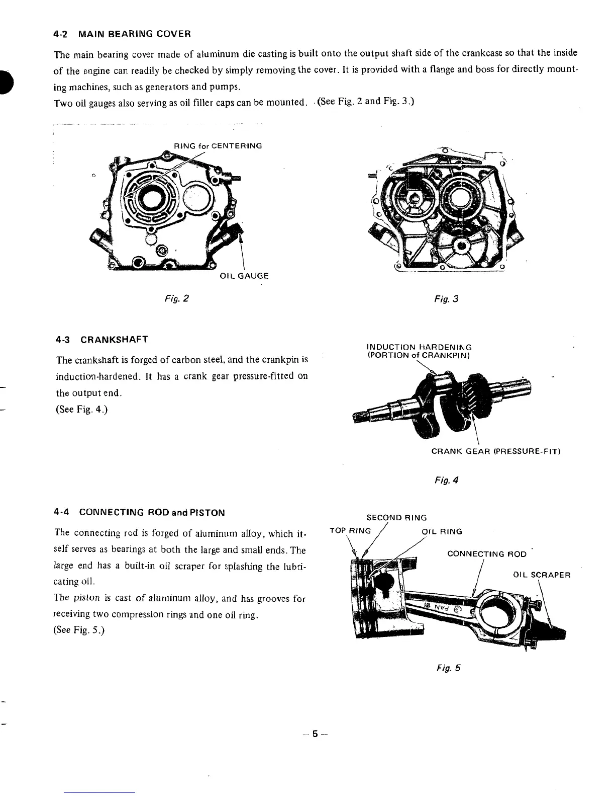
4-2
MAIN
BEARING COVER
B
The main bearing cover made of aluminum die casting is built onto the output shaft side of the crankcase
so
that the inside
of the engine can readily be checked by simply removing the cover. It is provided with a flange and boss for directly mount-
ing machines, such as generators and pumps.
Two
oil
gauges also serving as oil filler caps can be mounted.
.
(See Fig.
2
and Fig.
3
.)
RING
for
CENTERING
OIL
GAUGE
Fig.
2
Fig.
3
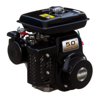
4-3
CRANKSHAFT
INDUCTION HARDENING
(PORTION
of
CRANKPIN)
The crankshaft
is
forged
of
carbon steel, and the crankpin
is
induction-hardened. It has a crank gear pressure-fitted on
the output end.
-
-
(See Fig.
4.)
CRANK GEAR (PRESSURE-FIT)
Fig.
4
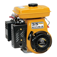
4-4
CONNECTING
ROD
and
PISTON
The
connecting
rod
is
forged
of
aluminum alloy, which it-
self serves as bearings at both the large and small ends. The
large end has
a
built-in
oil
scraper
for
splashng the
lubri-
cating
oil.
The
piston
is cast
of
aluminum alloy, and has grooves
for
receiving two compression rings and one
oil
ring.
(See
Fig.
5.)
SECOND
RING
Fig.
5
-5-