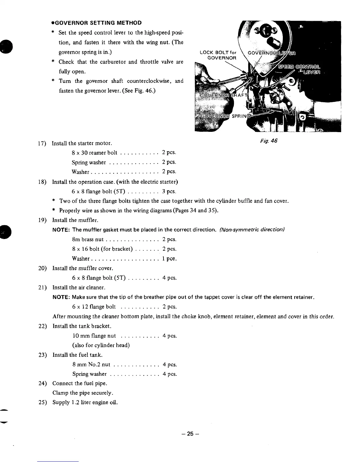
.GOVERNOR
SETTING METHOD
*
Set the speed control lever to the high-speed posi-
tion, and fasten it there with the wing nut. (The
governor spring
is
in.)
*
Check that the carburetor and throttle valve are
fully open.
*
Turn the governor shaft counterclockwise,
and
fasten the governor lever. (See Fig. 46.)
Fig.
46
Install the starter motor.
8
x
30
reamer bolt
...........
2
pcs.
Spring washer
..............
2
PcS.
Washer.
..................
2
pes.
Install the operation case. (with the electric starter)
6
x
8
flange bolt (5T)
.........
3
pcs.
*
Two of the three flange bolts tighten the case together with the cylinder buffle and fan cover.
*
Properly wire as shown in the wiring diagrams (Pages
34
and
35).
Install the muffler.
NOTE:
The muffler gasket must be placed
in
'the correct direction.
(Non-symmetric direction)
8m brass nut
...............
2 pcs.
8
x
16
bolt (for bracket)
.......
2
pcs.
Washer.
..................
1
pce.
Install the muffler cover.
6
x
8
flange bolt (5T)
.........
4
pcs.
Install the
air
cleaner.
NOTE:
Make sure that the tip of the breather pipe
out
of the tappet cover
is
clear off the element retainer.
6
x
12 flange bolt
...........
2
pcs.
After mounting the cleaner bottom plate, install the choke knob, element retainer, element and cover
in
ths order.
Install the tank bracket.
10
mm flange nut
...........
4
pcs.
(also for cylinder head)
Install the fuel tank.
8
mm
No.2
nut
.............
4
pcs.
Spring washer
..............
4
pcs.
Connect the fuel pipe.
Clamp the pipe securely.
Supply 1.2 liter engine
oil.
-25
-