4)
Tighten the cover bolt.
NOTE: The bolt cannot be tightened unless the front cover andrearcover are positioned correctly.
The shape of the cover bolt is shown below.
Table
10-3
1
MODEL
d
1
S
I
LG072
90
rnrn
15 mm
3.54 0.54
90
mm
15 mm
LG152. LGK152
1
E.:;
3.54
0.54
I
LG201, LG2OlD
i
:.:;
I
loo
3.94
mrn
i
l5
0.54
rnrn
I
I
LG301, LG301
D
I
E,:;
1
30
mm
I
l5
mm
5.1 2"
I
0.54
I
5)
LG152, LGK152, LG201, LG201D, LG301, LG301D has a stator cover which must be installed. Place it between
the stator and cover bolt, and fold the edge around it to fasten it.
10-3-5
BRUSH
HOLDER
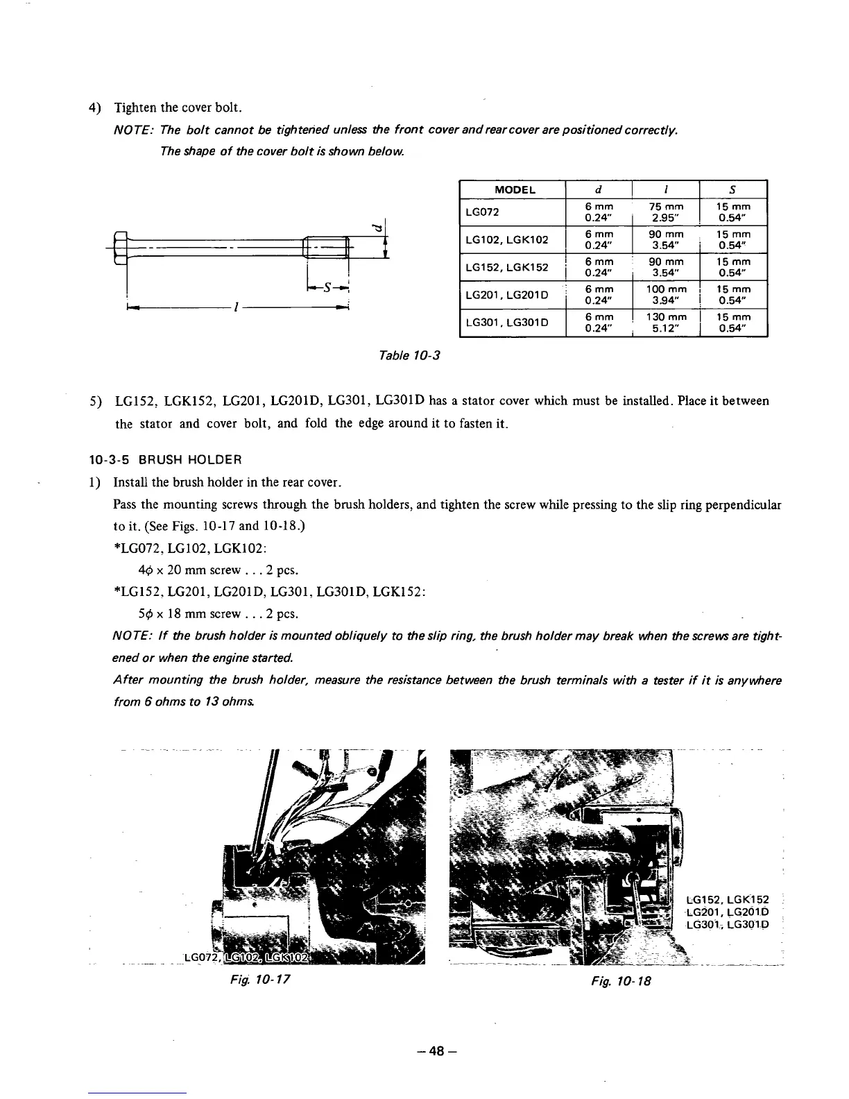
1) Install the brush holder in the rear cover.
Pass the mounting screws through the brush holders, and tighten the screw while pressing to the slip ring perpendicular
to
it. (See Figs. 10-17 and 10-18.)
*LG072, LG102, LGKl02:
4$
x
20
mm screw
.
.
.
2
pcs.
*LG152, LG201, LG201D, LG301, LG301D, LGKl52:
50
x
18 mm screw
.
.
.
2 pcs.
NOTE: If the brush holder
is
mounted obliquely to the slip ring, the brush holder may break when the screws are tight-
ened or when the engine started.
After mounting the brush holder, measure the resistance between the brush terminals with a tester if
it
is anywhere
from
6
ohms to
13
ohms
Fig:
10-
17
Fig.
10-
18
-48
-