5-3-3 DC OUTPUT
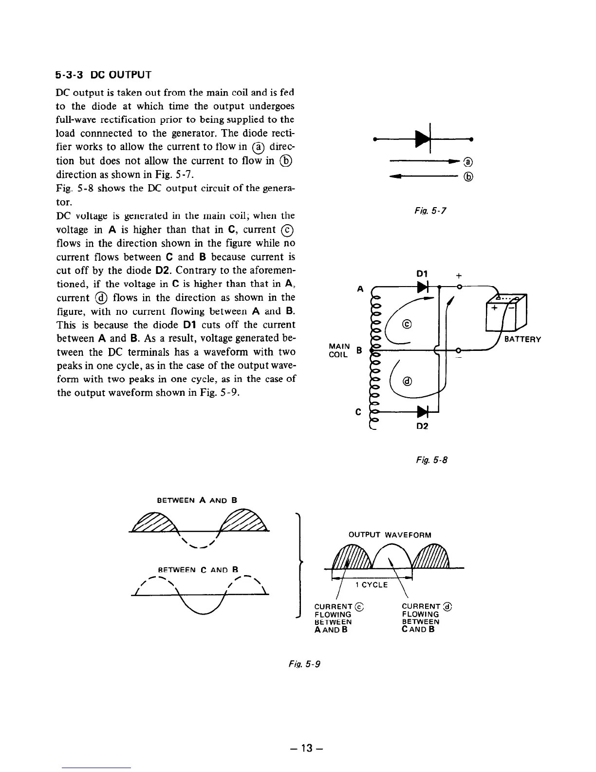
DC output is taken out from the main coil and is fed
to the diode at which time the output undergoes
full-wave rectification prior to being supplied to the
load connnected to the generator. The diode recti-
fier works to allow the current to flow in @ direc-
tion but does not allow the current to flow in @
direction as shown in Fig. 5-7.
Fig. 5-8 shows the DC output circuit of the genera-
tor.
DC voltage is generated in the main coil; when the
voltage in
A
is higher than that in C, current @
flows in the direction shown in the figure while no
current flows between C and
B
because current is
cut off by the diode
D2.
Contrary to the aforemen-
tioned, if the voltage in C is higher than that in
A,
current @ flows in the direction as shown in the
figure, with no current flowing between
A
and
B.
This is because the diode
Dl
cuts off the current
between
A
and
B.
As a result, voltage generated be-
tween the DC terminals has a waveform with two
peaks in one cycle, as in the case of the output wave-
form with two peaks in one cycle, as in the case of
the output waveform shown in Fig. 5-9.
Fig. 5-7
Dl
+
A
RY
MAIN B
COIL
Fig. 5-8
BETWEEN A AND B
OUTPUT WAVEFORM
BETWEEN C AND B
BETWEEN
BETWEEN
AAND B
CAND B
Fig. 5-9
-13-
 Loading...


