9-3 ROTOR
1) Unsolder the diode and the resistor from the ro-
tor terminal.
Unsolder one wire of each part.
E RECTIFIER
2) Check the resistance between the wire ends of
rotor winding at the terminals.
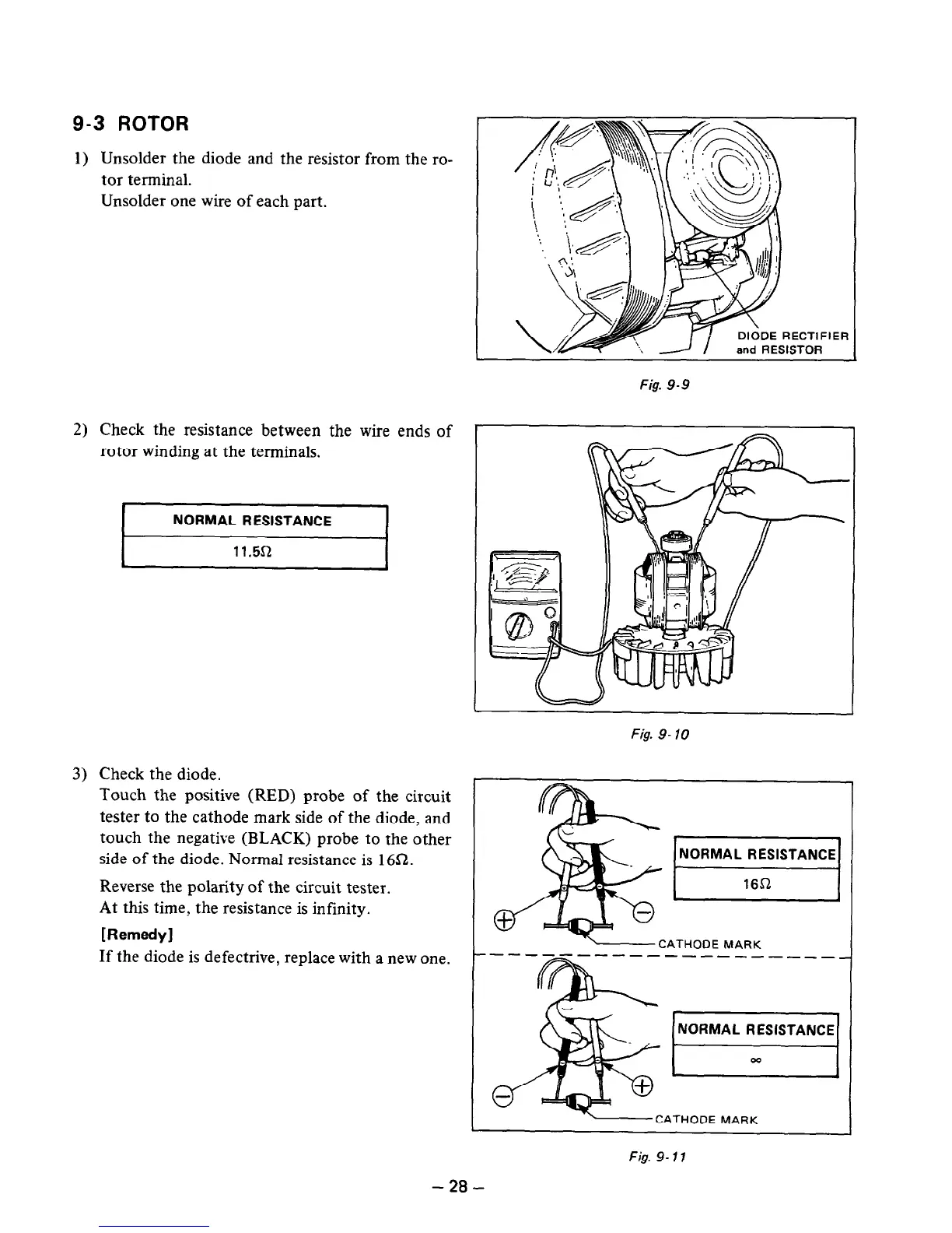
3)
Check the diode.
I
NORMAL RESISTANCE
I
I
11.5s2
I
Touch the positive (RED) probe of the circuit
tester to the cathode mark side of the diode, and
touch the negative (BLACK) probe to the other
side of the diode. Normal resistance is 16a.
Reverse the polarity of the circuit tester.
At this time, the resistance is infinity.
[RemeM
If the diode is defectrive, replace with a new one.
Fig. 9-9
~~-
Fig. 9- 10
1 NORMAL RESlSTANCEj
I
16S2
I
CATHODE MARK
Fig. 9-77
- 28 -

 Loading...


