10-6 FREQUENCY CHANGEOVER SYSTEM
(50 Hz/60 Hz Selectable Type)
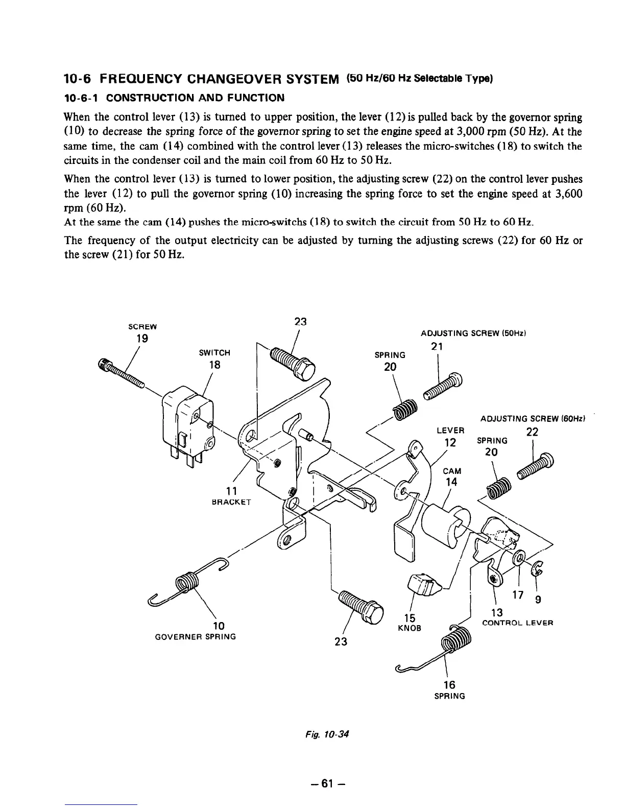
10-6-l CONSTRUCTION AND FUNCTION
When the control lever (13) is turned to upper position, the lever (12) is pulled back by the governor spring
(10) to decrease the spring force of the governor spring to set the engine speed at 3,000 r-pm (50 Hz). At the
same time, the cam (14) combined with the control lever (13) releases the micro-switches (18) to switch the
circuits in the condenser coil and the main coil from 60 Hz to 50 Hz.
When the control lever (13) is turned to lower position, the adjusting screw (22) on the control lever pushes
the lever (12) to pull the governor spring (10) increasing the spring force to set the engine speed at 3,600
rpm (60 Hz).
At the same the cam (14) pushes the micro-switchs (18) to switch the circuit from 50 Hz to 60 Hz.
The frequency of the output electricity can be adjusted by turning the adjusting screws (22) for 60 Hz or
the screw (21) for 50 Hz.
SCREW
23
.r\ I
ADJUSTING SCREW (50Hz)
SPRING
20
ADJUSTING SCREW
LEVER
22
17
SPRING
I
IU
GOVERNER SPRING
/
l5
/ CdN3TROL LEVER
23
(60Hd
16
SPRING
Fig. lo-34
-61 -