9. CHECKING FUNCTIONAL MEMBERS
9-l CONTROL PANEL
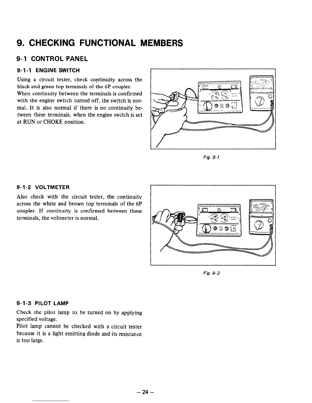
9- I- 1 ENGINE SWITCH
Using a circuit tester, check continuity across the
black and green top terminals of the 6P coupler.
When continuity between the terminals is confirmed
with the engine switch turned off, the switch is nor-
mal. It is also normal if there is no continuity be-
tween these terminals, when the engine switch is set
at RUN or CHOKE position.
9-l-2 VOLTMETER
Also check with the circuit tester, the continuity
across the white and brown top terminals of the 6P
coupler. If continuity is confirmed between these
terminals, the voltmeter is normal.
9-1-3 PILOT LAMP
Check the pilot lamp to be turned on by applying
specified voltage.
Pilot lamp cannot be checked with a circuit tester
because it is a light emitting diode and its resistance
is too large.
Fig. 9- 1
Fig. 9-2
- 24 -

 Loading...


