9-1-4 AC RECEPTACLES
Using a circuit tester, check continuity between the two terminals at the rear of the
AC
receptacles while the
receptacle is mounted on the control panel. When continuity is confirmed between the output terminals of
the receptacle with
a
wire connected across these terminals, the
AC
receptacle is normal. When the wire is re-
moved and no continuity is confirmed between these terminals, the receptacles are also normal.
Fig.
9-3
(A)
Fig.
9-3
(B)
9-1-5 DC TERMINALS
Using a circuit tester, check continuity between the
DC
terminals at the rear side of the control panel
while they are mounted on the panel.
When continuity is confirmed between the
DC
ter-
minals with a wire connected across these terminals,
the
DC
terminals are normal. When the wire is re-
moved and no continuity is confirmed between these
terminals, the terminals are also normal.
Fig.
9-4
J
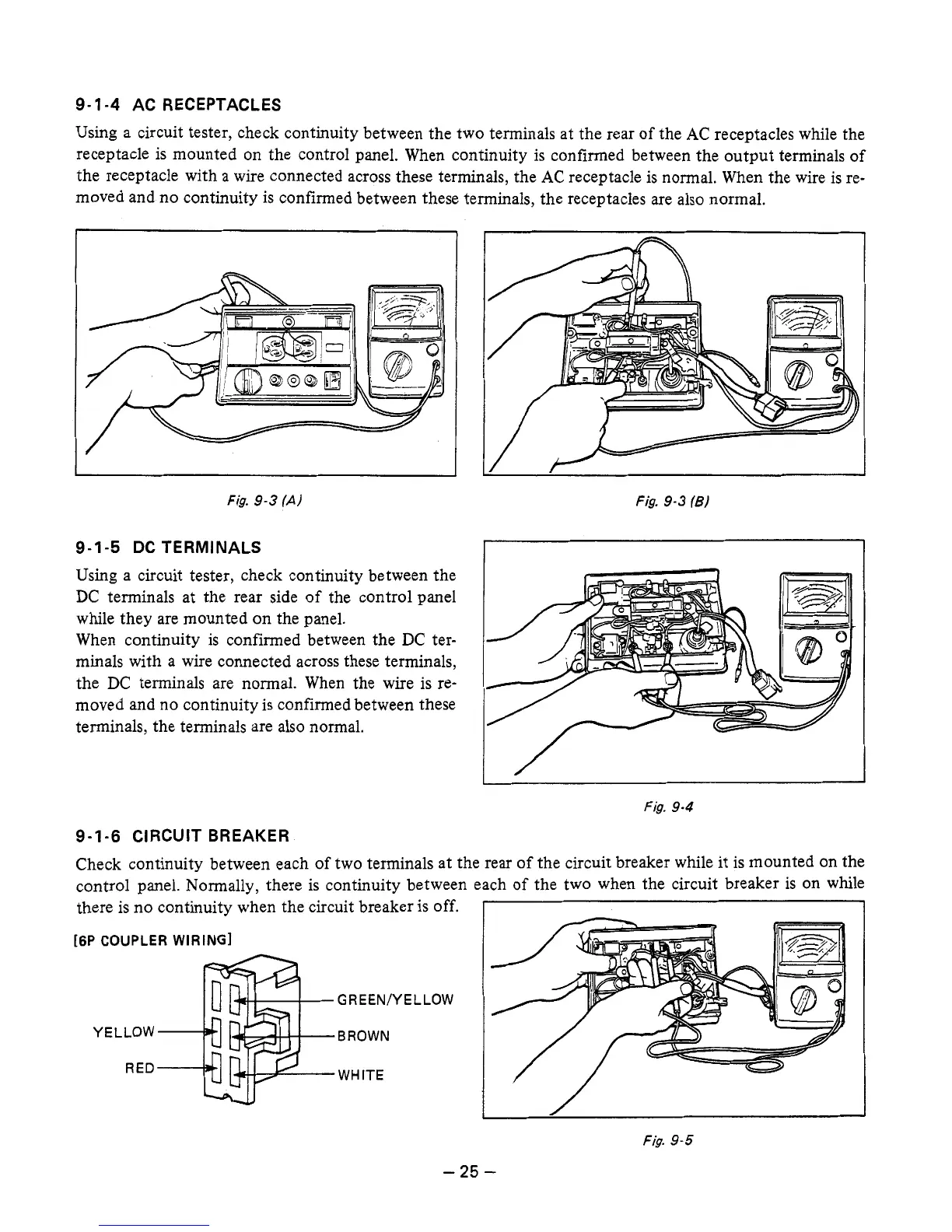
9-1-6 CIRCUIT BREAKER
Check continuity between each
of
two terminals at the rear of the circuit breaker while it is mounted on the
control panel. Normally, there is continuity between each of the two when the circuit breaker is on while
there is no continuity when the circuit breaker is off.
I
[6P COUPLER WIRING]
GREEN/YELLOW
YELLOW BROWN
RED
WHITE
Fig.
9-5
-
25
-

 Loading...


