10-3 DISASSEMBLY SEQUENCE
step
Part to remove
Description Precautions Necessary tools
1
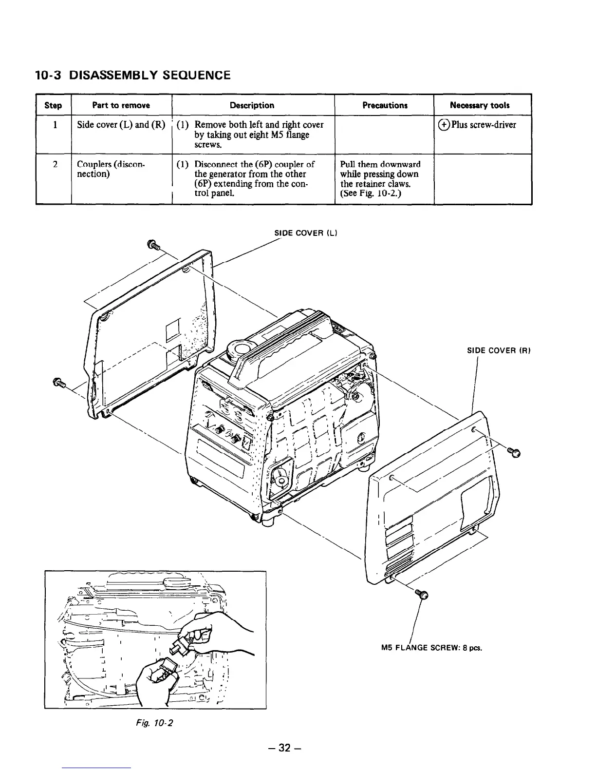
Side cover (L) and (R) ’ (1) Remove both left and right cover
0
+ Plus screw-driver
by taking out eight MS flange
screws.
2 Couplers (discon- (1) Disconnect the (6P) coupler of Pull them downward
nection) the generator from the other
(6P) extending from the con-
while pressing down
the retainer claws.
trol panel.
(See Fig. 10-2.)
SIDE COVER IL)
SIDE COVER (Ri
Fig. IO-2
M5 FLANGE SCREW: 8
PCS.
-
32
-
 Loading...


