5-3 DESCRIPTION OF GENERATOR OPERATION
INITIAL EXCITATION
STATOR
PERMANENT MAGNETO
FIELD COIL
ROTOR
-----
---
DIODE
CONDENSER COIL
L
------
A
Fig. 5-6
5-3-l GENERATION OF NO-LOAD VOLTAGE
1)
2)
3)
4)
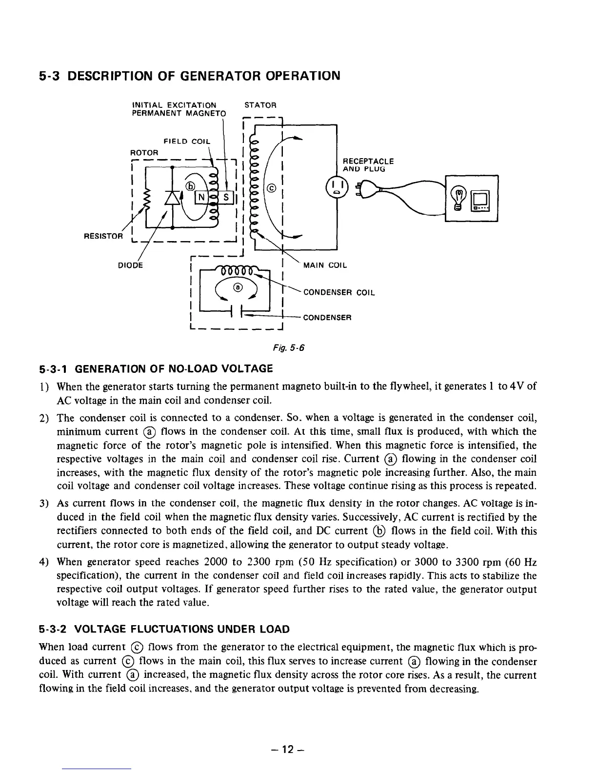
When the generator starts turning the permanent magneto built-in to the flywheel, it generates 1 to 4V of
AC voltage in the main coil and condenser coil.
The condenser coil is connected to a condenser. So. when a voltage is generated in the condenser coil,
minimum current @ flows in the condenser coil. At this time, small flux is produced, with which the
magnetic force of the rotor’s magnetic pole is intensified. When this magnetic force is intensified, the
respective voltages in the main coil and condenser coil rise. Current @ flowing in the condenser coil
increases, with the magnetic flux density of the rotor’s magnetic pole increasing further. Also, the main
coil voltage and condenser coil voltage increases. These voltage continue rising as this process is repeated.
As current flows in the condenser coil, the magnetic flux density in the rotor changes. AC voltage is in-
duced in the field coil when the magnetic flux density varies. Successively, AC current is rectified by the
rectifiers connected to both ends of the field coil, and DC current @ flows in the field coil. With this
current, the rotor core is magnetized, allowing the generator to output steady voltage.
When generator speed reaches 2000 to 2300 rpm (50 Hz specification) or 3000 to 3300 rpm (60 Hz
specification), the current in the condenser coil and field coil increases rapidly. This acts to stabilize the
respective coil output voltages. If generator speed further rises to the rated value, the generator output
voltage will reach the rated value.
5-3-2 VOLTAGE FLUCTUATIONS UNDER LOAD
When load current @ flows from the generator to the electrical equipment, the magnetic flux which is pro-
duced as current @ flows in the main coil, this flux serves to increase current @ flowing in the condenser
coil. With current @ increased, the magnetic flux density across the rotor core rises. As a result, the current
flowing in the field coil increases, and the generator output voltage is prevented from decreasing.
-12-

 Loading...


