8-2 MEASURING AC OUTPUT
TO A
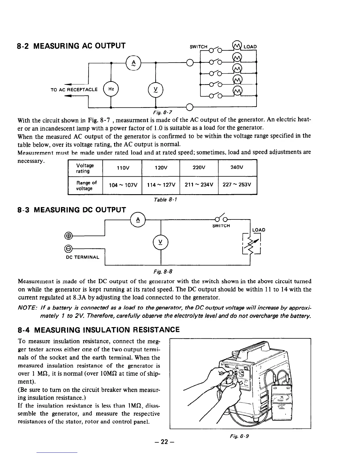
Fig. 8-7
With the circuit shown in Fig. 8-7 , measurment is made of the AC output of the generator. An electric heat-
er or an incandescent lamp with a power factor of 1 .O is suitable as a load for the generator.
When the measured AC output of the generator is confirmed to be within the voltage range specified in the
table below, over its voltage rating, the AC output is normal.
Measurement must be made under rated load and at rated speed; sometimes, load and speed adjustments are
necessary.
Voltage
rating
11ov 12ov
220v
240v
Range of
voltage
104 - 107v
114- 127V
211 N 234V 227 - 253V
Table 8- 1
8-3 MEASURING DC OUTPUT
SWITCH
@
@
DC TERMINAL
Fig. 8-8
Measurement is made of the DC output of the generator with the switch shown in the above circuit turned
on while the generator is kept running at its rated speed. The DC output should be within 11 to 14 with the
current regulated at 8.3A by adjusting the load connected to the generator.
NOTE: If a battery is connected as a load to the generator, the DC output voltage will increase by approxi-
mately 1 to 2V. Therefore, carefully observe the electrolyte level and do not overcharge the battery.
8-4 MEASURING INSULATION RESISTA
To measure insulation resistance, connect the meg-
ger tester across either one of the two output termi-
nals of the socket and the earth terminal. When the
measured insulation resistance of the generator is
over 1 Mfi2, it is normal (over lOM!2 at time of ship-
ment).
(Be sure to turn on the circuit breaker when measur-
ing insulation resistance.)
If the insulation resistance is less than lMS2, disas-
semble the generator, and measure the respective
resistances of the stator, rotor and control panel.
,NCE
Fig. 8-9
-22
-

 Loading...


