10-5 CARBURETOR
10-5-l FUNCTION AND COMPONENTS (See
Fig. 10-32)
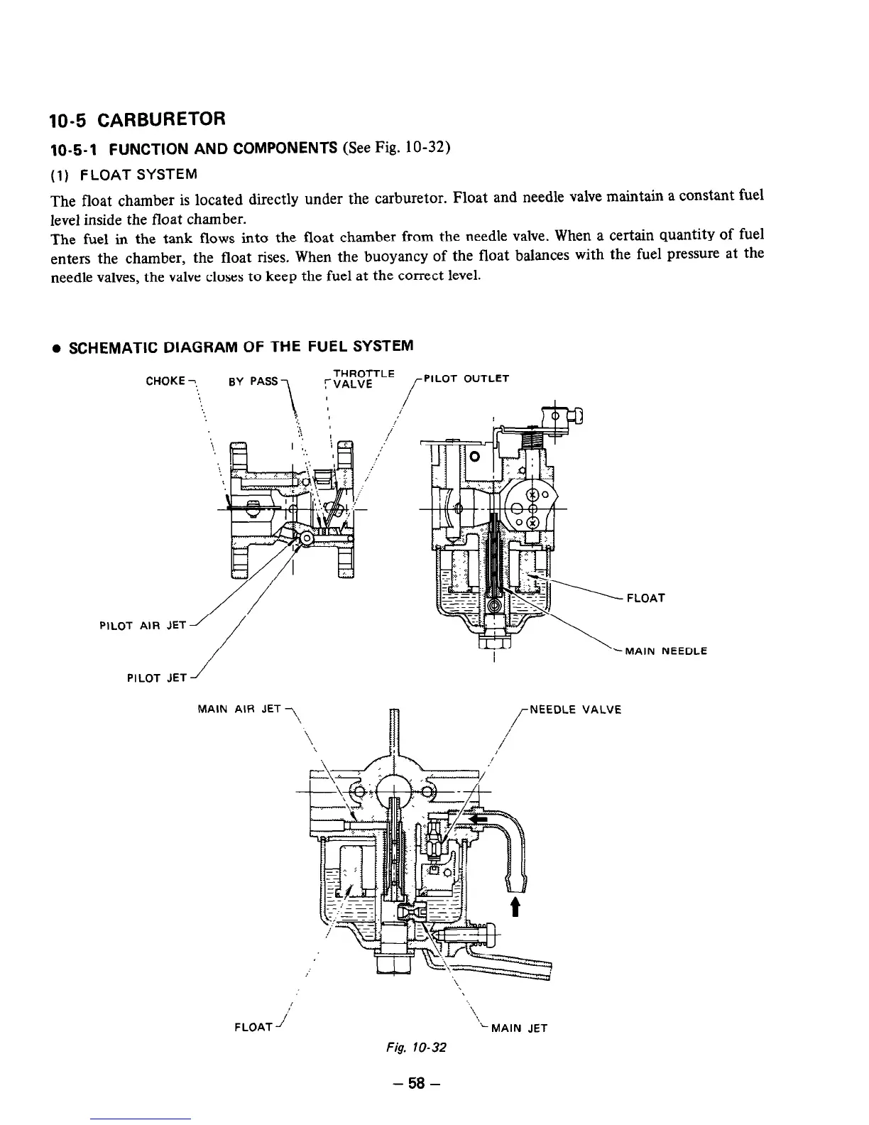
(1) FLOAT SYSTEM
The float chamber is located directly under the carburetor. Float and needle valve maintain a constant fuel
level inside the float chamber.
The fuel in the tank flows into the float chamber from the needle valve. When a certain quantity of fuel
enters the chamber, the float rises. When the buoyancy of the float balances with the fuel pressure at the
needle valves, the valve closes to keep the fuel at the correct level.
l
SCHEMATIC DIAGRAM OF THE FUEL SYSTEM
CHOKE
PILOT AIR JET
PILOT JET
?
BY PASS,
THROTTLE
‘VALVE
r PI LOT OUTLET
/
-
i
i
MAIN AIR JET
-
.,/
-
rNEEDLE
FLOAT -I’
‘1.
\
.-MAIN JET
Fig. IO-32
FLOA
T
MAIN
NEEDLE
VALVE
- 58 -

 Loading...


