8-2
AC OUTPUT MEASURING
TO
AC
RECEPTACLE
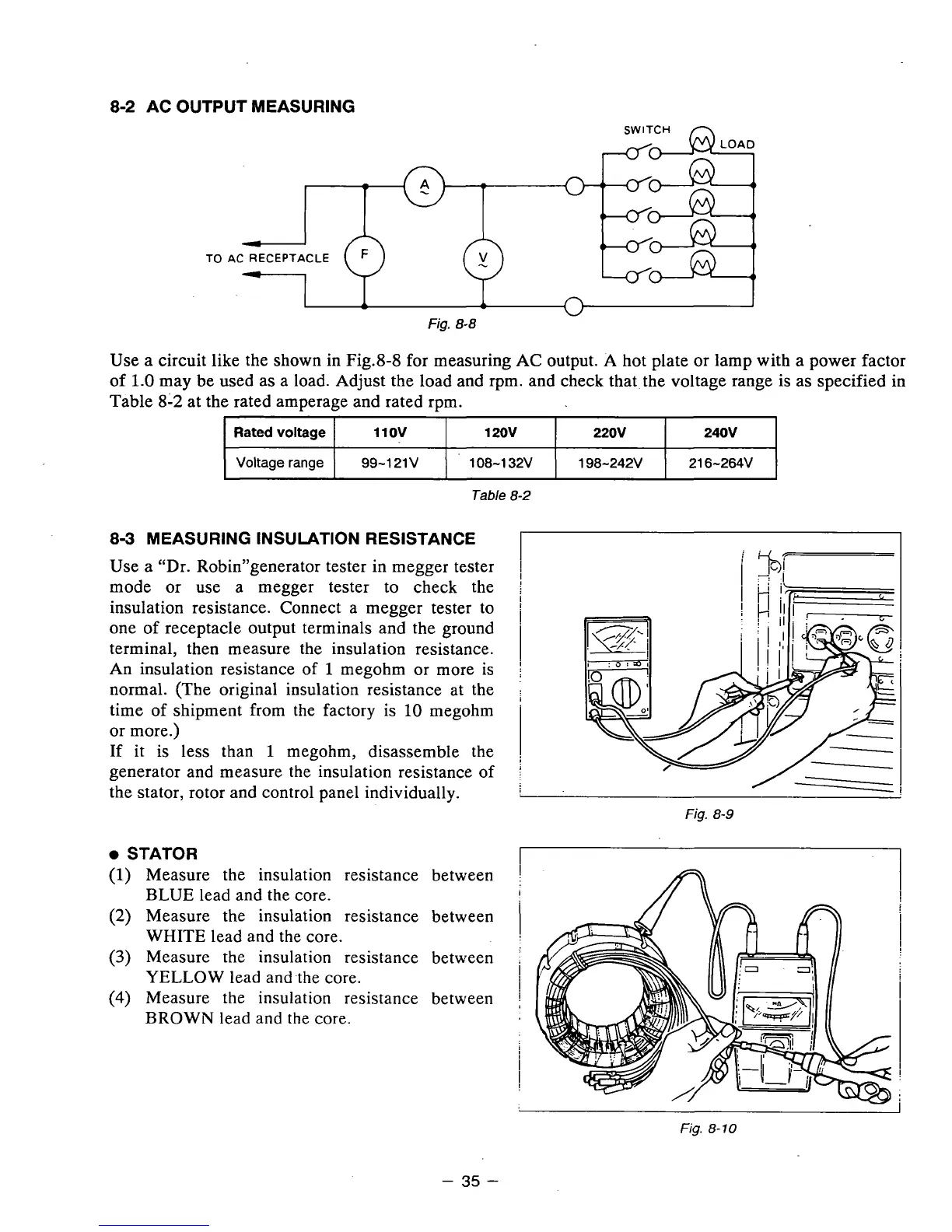
Fig.
8-8
Use
a
circuit like the shown in Fig.8-8 for measuring AC output. A hot plate
or
lamp with a power factor
of
1.0
may be used as a load. Adjust the load and rpm. and check that the voltage range is as specified in
Table
8-2
at the rated amperage and rated rpm.
Rated
voltage
21 6-264V 198-242V 108-1 32V 99-121V
Voltage range
240V
220v
1 20v 110v
Table
8-2
8-3
MEASURING INSULATION RESISTANCE
Use
a
"Dr. Robin"generator tester in megger tester
mode
or
use a megger tester to check the
insulation resistance. Connect a megger tester to
one of receptacle. output terminals and the ground
terminal, then measure the insulation resistance.
An insulation resistance
of
1
megohm
or
more is
normal. (The original insulation resistance at the
time of shipment from the factory
is
10
megohm
or more.)
If
it is less than
1
megohm, disassemble the
generator and measure the insulation resistance of
the stator, rotor and control panel individually.
0
STATOR
(1)
Measure the insulation resistance between
(2)
Measure the insulation resistance between
(3)
Measure the insulation resistance between
(4)
lMeasure the insulation resistance between
BLUE lead and the core.
WHITE lead and the core.
YELLOW lead and -the core.
BROWN lead and the core.
Fig.
8-10
-
35
-