10-4-9 FRONT PANEL
-Mount the front panel assembly to the frame.
Refer to Section
10-5
for disassembly, checking and reassembly procedures of the front panel.
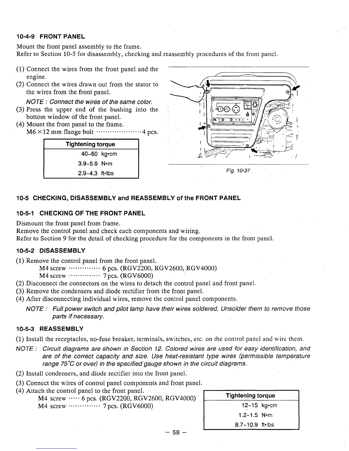
(1)
Connect the wires from the front panel and the
engine.
(2) Connect the wires drawn out from the stator
to
the wires from the front panel.
NOTE
:
Connect the wires of the same color.
(3)
Press the upper end of the bushing into the
bottom window of the front panel.
(4) Mount the front panel to the frame.
M6
X
12
mm flange bolt
....................
4 pcs.
3.9-5.9
Nom
Fig.
10-37
10-5 CHECKING, DISASSEMBLY
and
REASSEMBLY
of
the
FRONT PANEL
10-5-1 CHECKING OF THE FRONT PANEL
Dismount the front panel from frame.
Remove the control panel and check each components and wiring.
Refer to Section
9
for the detail of checking procedure for the components in the front panel.
10-5-2
DISASSEMBLY
(1)
Remove the control panel from the front panel.
344scre~~
..............
6
pcs. (RGV2200, RGV2600, RGV4000)
344screLy
..............
7
pcs. (RGV6000)
(2) Disconnect-the connectors on the wires to detach the control panel and front panel.
(3)
Remove the condensers and diode rectifier from the front panel.
(4) After disconnecting individual wires, remove the control panel components.
NOTE
:
Full power switch and pilot lamp have their wires soldered. Unsolder them to remove those
parts if necessary.
10-5-3 REASSEMBLY
(1)
Install the receptacles, no-fuse breaker, terminals, switches, etc. on the control panel and wirz them.
NOTE
:
Circuit diagrams are shown in Section
12.
Colored wires are used for easy identification, and
are of the correct capacity and size. Use heat-resistant type wires (permissible temperature
range 75°C or over) in the specified gauge shown. in the circuit diagrams.
(2)
Install condensers, and diode rectifier into the front panel.
(3)
Connect the wires of control panel components and front panel.
(4)
Attach the control panel to the front panel.
M4 screw
.....
6 pcs. (RGV2200, RGV2600, RGV4000)
M4 Screw
..............
7
pcs. (RGV6000)
1.2-1.5
Nom
-
58
-