9-5
ROTOR
ASSEMBLY
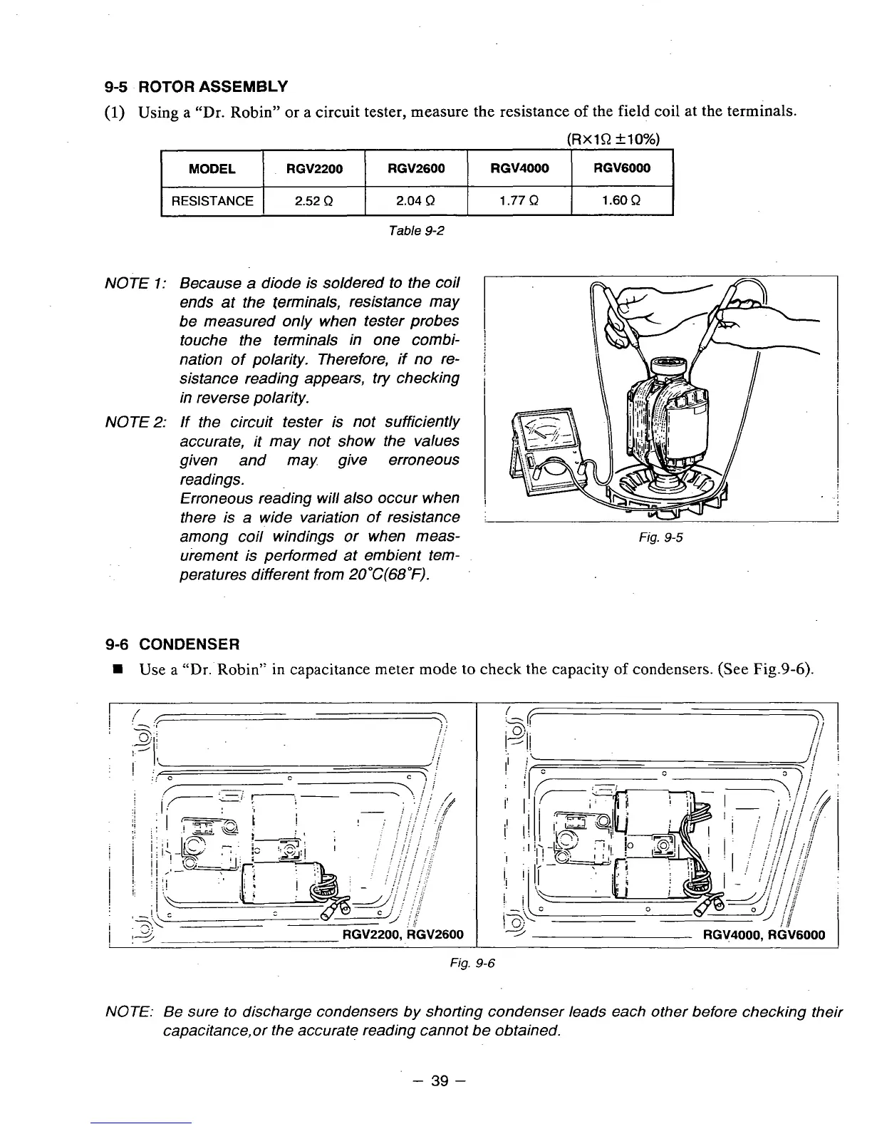
(1)
Using a "Dr.
Robin"
or a circuit tester, measure the resistance
of
the field coil
at
the terminals.
(RxlQ
&lo%)
MODEL
RGV6000
RGV4000 RGV2600
RGV2200
RESISTANCE
I
2.52
R
1.60
R
1.77
R
2.04
R
I
Table
9-2
NOTE
1:
Because
a
diode is soldered to the coil
ends at the terminals, resistance may
be measured only when tester probes
touche the terminals in one combi-
nation of polarity. Therefore, if no re-
sistance reading appears, try checking
in reverse polarity.
NOTE
2:
If the circuit tester is not sufficiently
accurate, it may not show the values
given and may give erroneous
readings.
Erroneous reading will also occur when
there is a wide variation of resistance
among coil windings or when meas-
urement is performed at embient tem-
peratures different from
2OoC(68"F).
9-6
CONDENSER
W
Use a
"Dr.
Robin" in capacitance meter mode
to
check the capacity
of
condensers. (See Fig.9-6).
Fig.
9-6
3
RGV4000, RGV6000
I
NOTE:
Be sure to discharge condensers by shorting condenser leads each other before checking their
capacitance,or the accurate reading cannot be obtained.
-
39
-