Specifications
3-1 Robostar Co., Ltd
Chapter 3. Specifications
3.1 Profibus Option Card Specifications
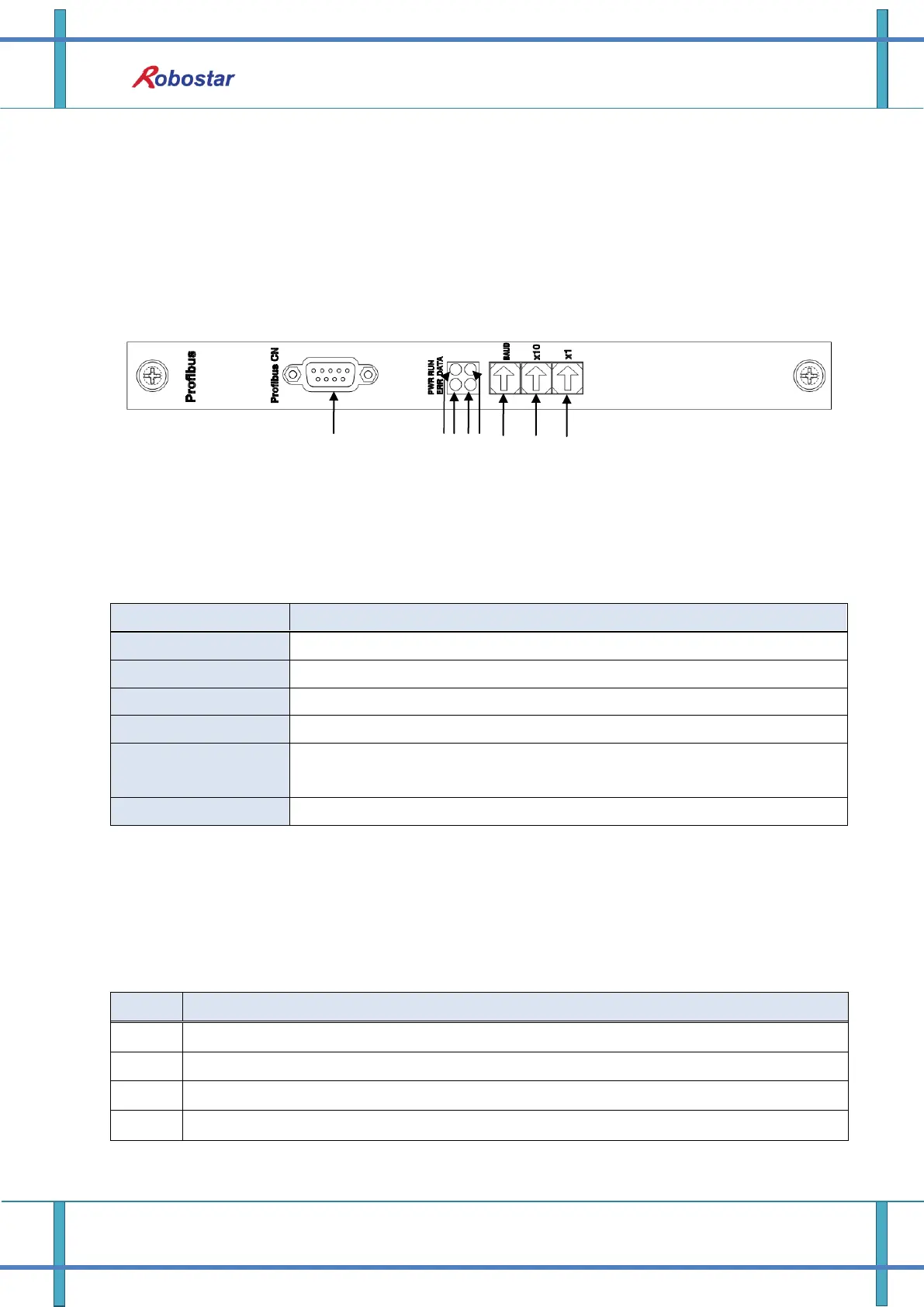
Fig. 3.1 shows the front view of Profibus Option Card.
Fig. 3.1 Block Diagram of Profibus Option Card
Table 3.1 shows Profibus Option Card specifications.
RS485-based Profibus-DP protocol Interface
Internal +5V ±5% : 0.5A nominal Maximum
Temperature : operating 0 ~ 40℃
Storage -15 ~ 60℃
Humidity : 20 ~ 85% (non-condensing)
Table 3.1 Profibus Option Card Specifications
3.2 Description of LED Functions
The status of Profibus Option Card can be simply known from the outside through the status display
LED attached to Profibus Option Card.
Represents current data being exchanged by being connected to Profibus Network
Represents Profibus Option Card under normal operation
Represents status of Profibus communication alarm
Represents status for power supply to Profibus Option Card
Table 3.2 Description of LED Status on Profibus Option Card
ProfiBus
Communication
Connector
Station 1x
Rotary Switch
Station 10x
Rotary Switch
Baudrate
Rotary Switch
 Loading...