Installation and Operation Setting
4-2 Robostar Co., Ltd
4.2 How to Connect Profibus Network Cable
When wiring the profibus cable, make a connection suitable for pin map in Table 4.1. In high-speed
communication, be sure to use cables and connectors in accordance with communication standards.
Receive Data/Transmission Data+
Ground in data transmission (5V ground)
Voltage supplied to terminating resistance (P5V)
Receive Data/Transmission Data+
Table 4.1 Signals from Profibus Connector per Pin
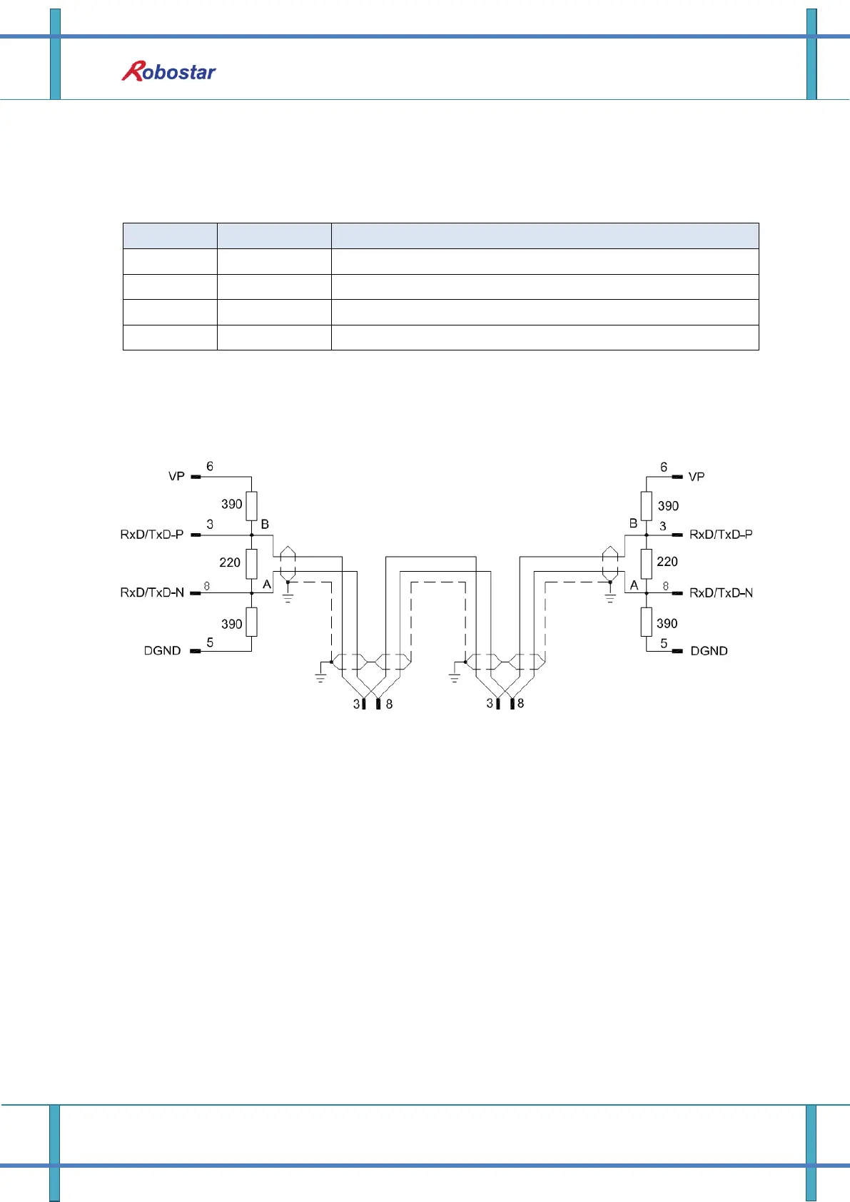
For examples of how to connect the cable, refer to “Fig. 4.2 How to Wire Cable”.
Fig. 4.2 How to Wire Cable
 Loading...