Installation and Operation Setting
4-5 Robostar Co., Ltd
4.3.2 USER I/O Setting
Below is a setup method for using User I/O as communications.
1. Setting Procedure
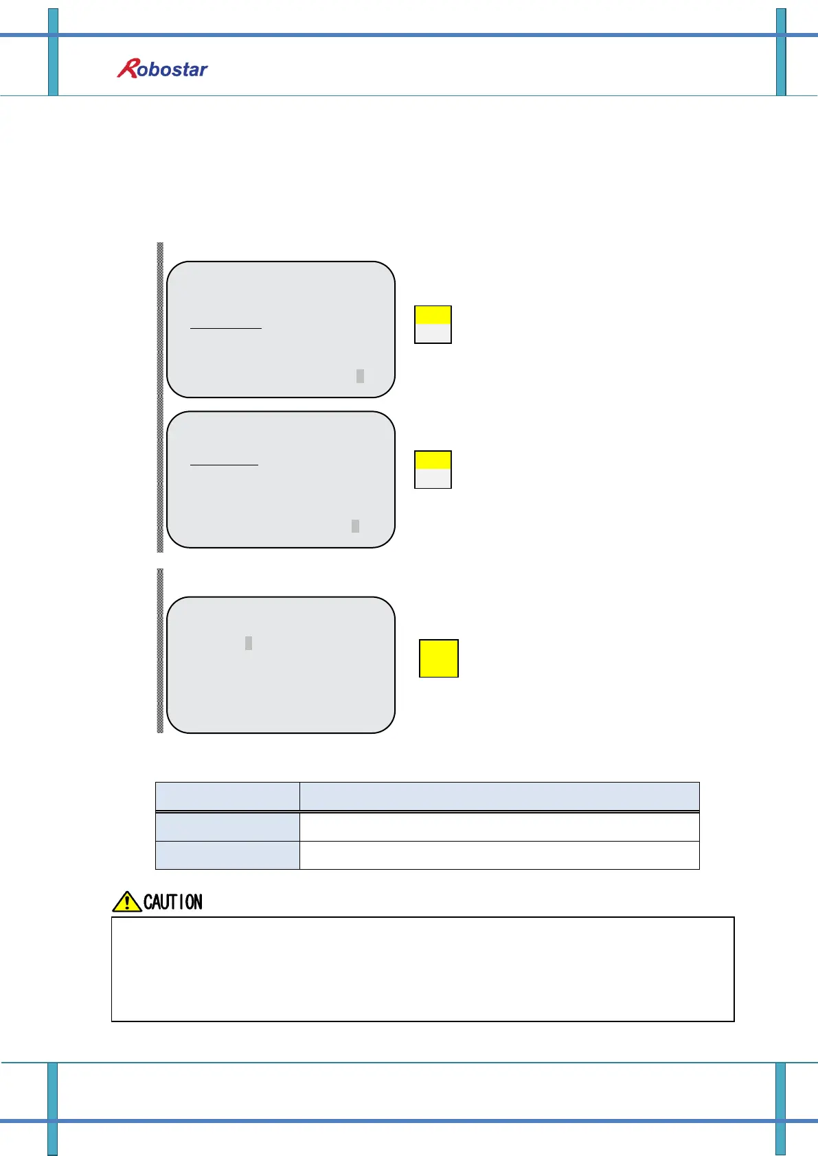
Step1. Move to USER I/O screen
Step2. USER I/O setup screen
This provides how to use USER I/O when using Field Bus card.
Input/output using USER I/O of N1 System IO B/D
Input/output using USER I/O of Field Bus card
<COM-FDBUS>
1: CARD
2: USER I./O
3: PROFIBUS ENDIAN
4: MAP EXTENTION
input #
<FDBUS-USER I/O>
USER IN/OUT SEL
USER IO : SYS U I/O
Select SYS U I/O” or “FIELD U I/O
<HW CONF - COM>
COMMUNICATION SET
1: RS232C
2: FIELD BUS
3: LINE SEPARATOR
group #
Open COMM screen
Select 2: FIELD BUS
Data(USER I/O area) input/output are restricted due to communications in setting SYS
USER I/O.
Data(User I/O) input/output are restricted through I/O Board in setting FIELDBUS USER I/O
For further details about User I/O, refer to “Handling Manual 3.3.6”.
 Loading...