24
1 CHACTERISTICS OF KRVS
1.1 Functional principle
KRVS is vacuum unit consisting of RVS series single stage liquid ring pump
completed of liquid-gas separator for partial recirculation of service liquid and
connecting piping (/P); in total recirculation version (/T) the unit is provided with
shell and tube heat exchanger for liquid ring cooling.
This manual is valid for KRVS unit with RVS liquid ring vacuum pump in all
versions, from size 7 to 60, in the material executions indicated in par. 1.2
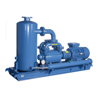
The pump of RVS series is a single-stage liquid ring pump with automatic
discharge valve. The pump consists of a cylindrical element 1 wherein the
impeller 2 rotates eccentrically.The impeller moves the service liquid, which,
because of the centrifugal force, turns into ring 3, concentric to the cylindrical
element.The gas is sucked through the inlet opening 4 on the front plate, than it
is compressed (5) and dischargeds through the pump discharge opening.
In units KRVS 7 to 21 the pump is located above the separator tank which acts
as the base of the unit while in the group 23 to 40 KRVS the tank is positioned in
side of the pump. The separator tank provides both the separation of the gaseous
phase from the liquid phase that an extremely low noise level. During the
exercise, the liquid ring pump is continuously fed with the service liquid which is
discharged, together with the gas, in the separator tank and then recirculated to the pump .The service liquid gets warmer because of the
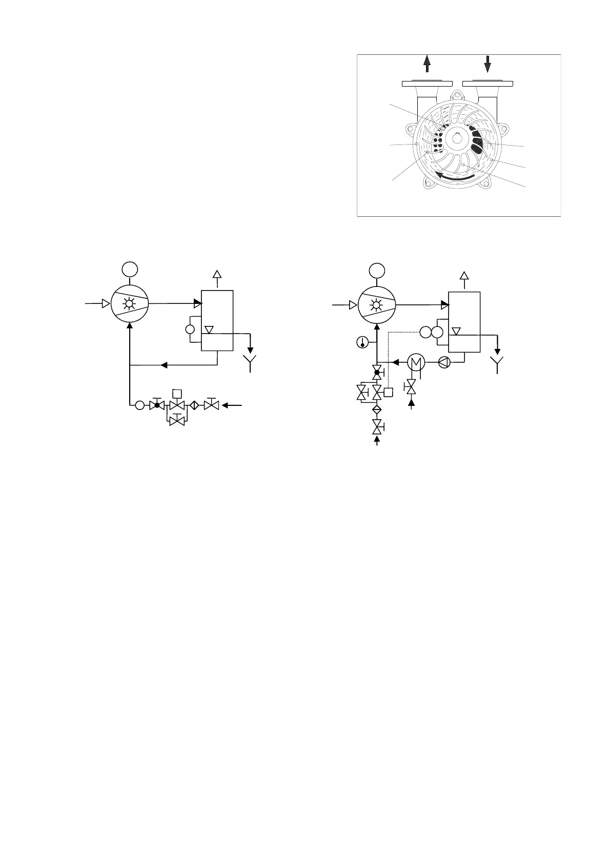
gas compressione generated heath. In order to avoid the service liquid overheating you can consider two systems: Continuous renewall
of liquid ring with fresh service liquid ( KRVS / P) as shown in figure 1.
Cooling of the service liquid by the coolant fluid in the heat exchanger ( KRVS / T ) as shown in fig.2 .
Fig.1 KRVS/P Fig.2 KRVS/T
1Pump
2 separator tank
3 Flow (by the customer)
4 Control valve (by the customer)
5 solenoid valve (by the customer)
6 by-pass valve (by the customer)
7 Filter (by the customer)
8 Shut-off valve (by the customer)
9 Circulating pump (optional)
10 Heat Exchanger
11 coolant valve (by the customer)
12 Control valve (by the customer)
13 Thermometer
14 Level switch (by the customer)
15 Level indicator (optional)
1.2 Construction
1.2.1 Bearing bracket
The close coupled pump version /M (size 7,14,16) is directly coupled to the flange of a standardized electric motor UNEL-MEC B35 and
the overhang impeller is supported by the electric motor bearings.
The pump with bearing bracket version /SG (size 7,14,16,17,21) is overhang supported by a cast iron bracket with two sealed ball bearings
life lubricated with grease.
For the pumps size 23,25,30,40 the impeller is mounted between two cast iron bearing brackets, with bearings grease lubricated (sealed
and life lubricated for sizes 23-25, and lubricated by a lubricator for sizes 30, 40 and 60).
1.2.2 Shaft seal
Up to size 25 the shaft is sealed by single mechanical seal according to EN 12756 flushed by pump’s service liquid.
Shafts of sizes 30, 40 and 60 can be sealed by: soft packing, single or double mechanical seal flushed by service liquid or by an external
source of clean liquid.
The shaft is not in contact with the pumped liquid or gas (sizes 23,25 excluded).
2
Overflow
Service
liquid
M
Cooling liquid
2
Make up liquid
M
Overflow
ASPIRAZIONESCARICO
1
6
2
4
3
5
Discharge
Suction
Compression