29
4 INSTALLATION
4.1 On-site installation
KRVS has to be installed in a free and clean site. The installing space must grant sufficient
ventilation for the electric motor.
Set KRVS horizontally on an even surface (max 5 mm on 1m) made out of concrete or
with a steel frame. If necessary use dampers between the unit and the floor. Fix KRVS
using four expansion anchor bolts through the relevant holes.
The overall dimensions of the unit are given in technical table
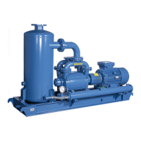
For sizes 23 to 60 put the pump horizontal (max 5 mm on 1m) using shims under the base
and near the foundation bolts (Fig. 6).
Pour the concrete into the holes in the foundation, and after the concrete has hardened (at
least 48 hours) tighten the mounting bolts. Verify that the pump rotates freely by hand. Check
the alignment (see section 4.2.1)
Warning : Ask Robuschi to install KRVS on a metallic structure
Note: Should the pump not be positioned horizontally, please consult us
NOTE for units KRVS 7
21: after installing the unit, check that separator tank is perfectly horizontally
aligned. If required use spacers under the baseplate in order to obtain the horizontal alignment
In case of outdoor installation adopt the following measures
CLIMATIC CONDITIONS MEASURES
Strong sunlight Protect with a canopy
Rainy / Snow Protect with a canopy
Temperature < - 20 °C Use only GRBS-CRBS and heat inside air before any start-up
Wind > 20 m/s Protect with windbreak walls
Hoarfrost Heat inlet silencer
Dust / Sand storm Special filter with preseparator
Note : For different climatic conditions contact ROBUSCHI ( or an authorized distributor )
4.2 Connections
The main connections are those given in the technical
table
To connect main piping, follow with care instructions
below:
Remove flange protections only before connecting
pipes.
Discharge pipe shall discharge to the atmosphere, if not
it has to be protected from overpressure by mean of a
safety valve.
Install a strainer in the suction piping Check that the
diameters of the pipes are not less than the diameters
of the pump flanges.
Clean the piping and remove welding scales, nuts, bolts
and rags.
Check by the arrows on the pump flanges the correct
position of the suction and discharge.
Check that corresponding flanges match perfectly.
Check that gaskets do not protrude into the pipes.
Avoid stress caused by the piping on the pump flanges
due to their weight or thermal distortion.
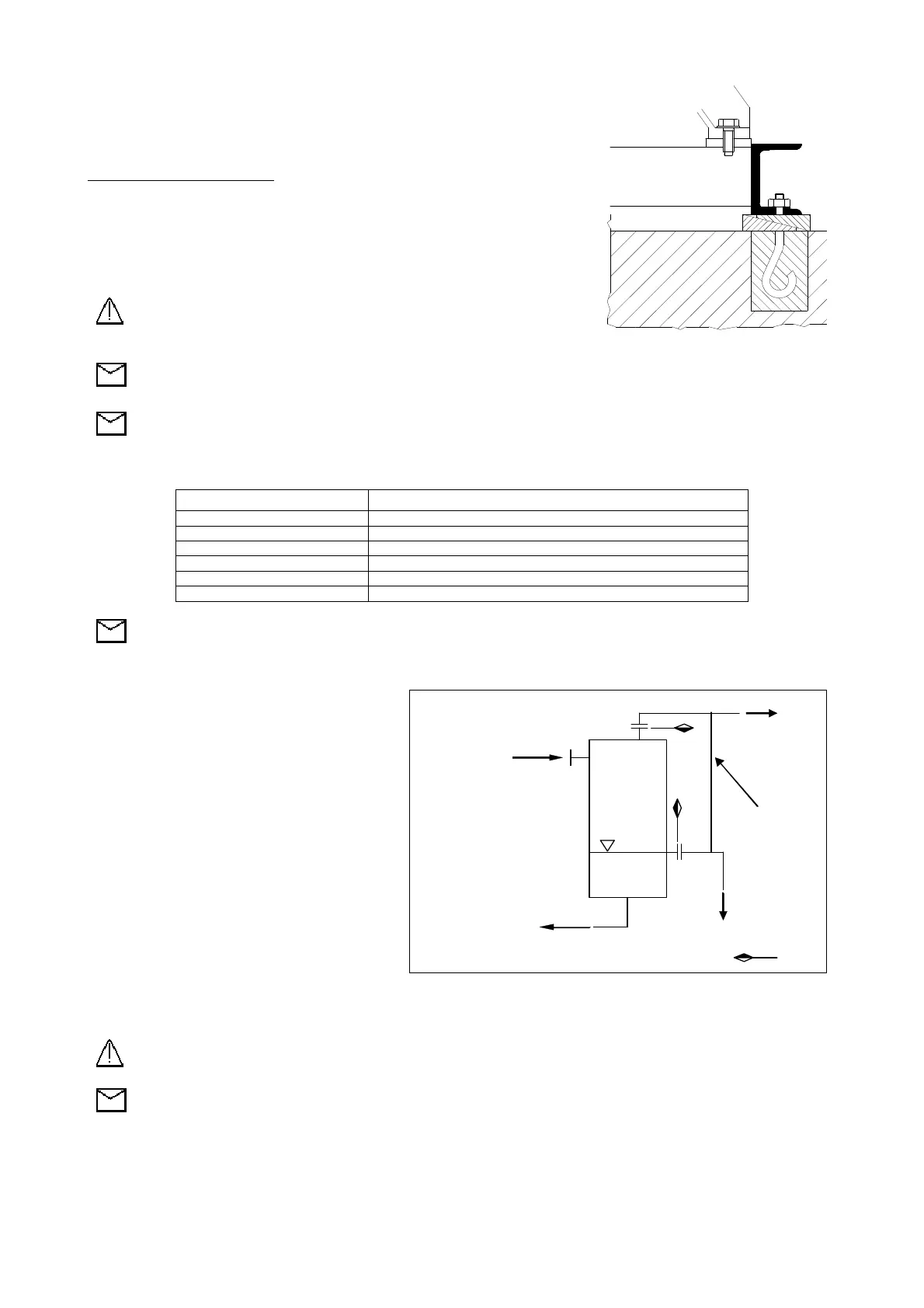
compressed gas far from people operating in the room where the unit is
installed, connect a suitable pipe to the discharge of separator tank with the same diameter
NOTE : The separator tank overflow is designed to discharge the excess of liquid at
pressure directly in a drain funnel. If the overflow is close-connected with a pipe it is necessary to
connect the last with the to the gas discharge pipe by a little tube (see fig. 7) in order to avoid the
siphon priming that in few minutes would empty the tank
4.2 Motor coupling
If the motor is installed by customer the coupling must be done following the instructions indicated in section 6.2.
Fig. 6
To the heat exchanger
or liquid ring pump
From liquid
ring pump
breaker
connection
Supply limit
Fig. 7