15
GB
Fig. 3
Fig. 4
Fig. 4 bis
Locating indoor unit
1. Do not place objects near the air dis-
charge so the air may be distributed
throughout the room.
2. Make sure the indoor unit is installed
firmly and in horizontal position.
3. Select a location that can support 4
times the weight of the unit so as to de-
crease noise level due to vibration.
4. Select a location where it is easy to in-
stall the drain, and as close to the out-
door unit as possible.
5. Make sure there is sufficient clearance
for all maintenance servicing.
6. Make sure the suspension system can
support 4 times the weight of the unit so
as to avoid saturation (permanent com-
pression).
Note:
1. Keep a reasonable distance from the
kitchen.
2. This equipment should not be installed
in laundry rooms.
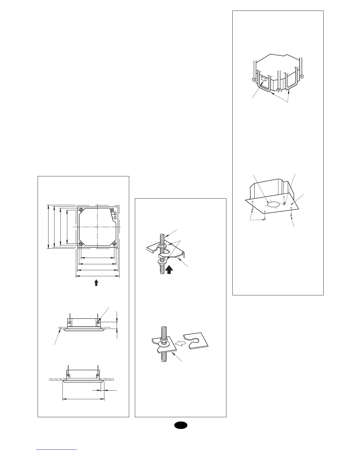
Opening in the ceiling and sus-
pension bolts (M10) (Fig. 3)
Installing the indoor unit (Fig. 4
and 4a)
1. Locate the indoor unit.
- Fasten the support to the fastening bolts.
Make sure they are firm and use nuts
and washers on both top and bottom of
the support. The fastening plate or fas-
teners (1) avoid movement of the wash-
ers.
- Use template (2) to establish the dimen-
sions of the opening in the ceiling.
- The centre of both the opening in the
ceiling as well as the unit are indicated
on the template supplied with this equip-
ment.
- Fasten the template to the indoor unit
with screws (3) x 3.
2. Locate the unit in correct position for in-
stallation.
3. Make sure the unit is in horizontal posi-
tion (with a level).
- The indoor unit is equipped with a pump
and float at each one of the four corners.
Check correct positioning with a level or
vinyl pipe. (If the unit is installed con-
trary to condensed water flow, the float
will not operate correctly and could
cause water spilling.)
4. Remove the fastener from washers (1)
and screw in the top nut.
5. Remove the installation template (2).
Attention: Tighten the nuts to make sure
the unit does not fall.
Cooling connections (Fig. 5)
- Use both wrenches at the same time, as
shown in the following illustrations, to con-
nect and disconnect the cooling pipes.
- See Table 1 to determine correct torque
to be applied to the nuts. (Tightening in
excess could cause gas leaks.)
- When connecting pipes, cover both the
outer as well as inner sides of the pipes
with cooling machine oil, and tighten them
manually 3 or 4 turns.
- Check pipe connections for gas leaks, and
lay them as indicated below.
- Use the sealing filler (11) to insulate con-
nection (8).
- On installations with a length of over 10
metres, add 30 g. per each metre over
780 FASTENING
840 INDOOR UNIT
890 OPENING IN THE CEILING
950 FRONT PANEL
780 FASTENING
840 INDOOR UNIT
890 OPENING IN THE CEILING
950 FRONT PANEL
A
160
VIEW FROM “A”
FASTENING
CEILING
FASTENING
SUPPORT
TIGHTEN WITH
TWO NUTS
WASHER (INCLUDED)
M10 BOLT
WASHER
FASTENER (1)
INSERT
VINYL PIPE
WATER
LEVER
SCREWS (3)
CENTRE OF OPENING
IN THE CEILING
BOLTS IN THE
INSTALLATION
TEMPLATE (2)
SCREWS (3)
POSITION CORNERS
OF DRAIN SYSTEM
950
> 20