17
GB
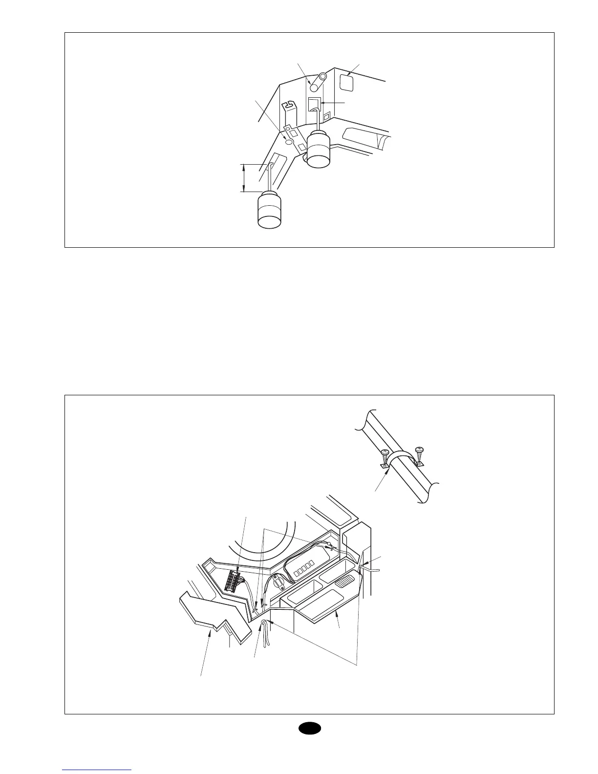
Fig. 10
Fig. 11
Method for adding water (Fig. 10)
Electrical connection
Attention: Before accessing terminals, dis-
connect power supply.
- All accessories and materials supplied
with this equipment are in compliance with
local regulations.
- For electrical connection, see the wiring
diagram inside the unit.
- Electrical connection should be carried
out by authorized personnel.
- A differential switch capable of turning the
entire system off should be installed.
- Grounding should be correct.
- Electrical connection should comply with
regulations in force.
- The switch installed should not exceed 30
mA.
- Should the power supply cable be dam-
aged, qualified personnel should replaced
it with an original cable.
Unit and controller connections (Fig. 11)
- Remove cover (1) and insert the cables
through the protection jacket 1, and con-
nect in accordance with the indoor unit
wiring diagram. Fasten with the clip.
- Remove cover (2) and insert the cables
through the protection jacket 2, and con-
nect to the controller.
- Cover cables with insulation.
- After wiring, fasten with clamps and re-
place covers 1 and 2.
- For cool/heat systems: Connect the 5 ter-
minals correctly.
- For cool only systems: Connect the 3 ter-
minals correctly.
DRAIN
HOSE
DRAIN SERVICE
OUTLET
ADDING WATER
THROUGH THE
INSPECTION HOLE
100 mm
INSPECTION
HOLE
SERVICE
COVER
PROTECTION
JACKET 2
CONTROL BOX
2 COVER
PRETECTION
JACKET 1
CONTROL BOX 1 COVER
SEAL HERE TO
AVOID LEAKS
CONNECTING TERMINALS
3 - FOR COOL / HEAT
5 - FOR COOL ONLY
CLAMP