16
GB
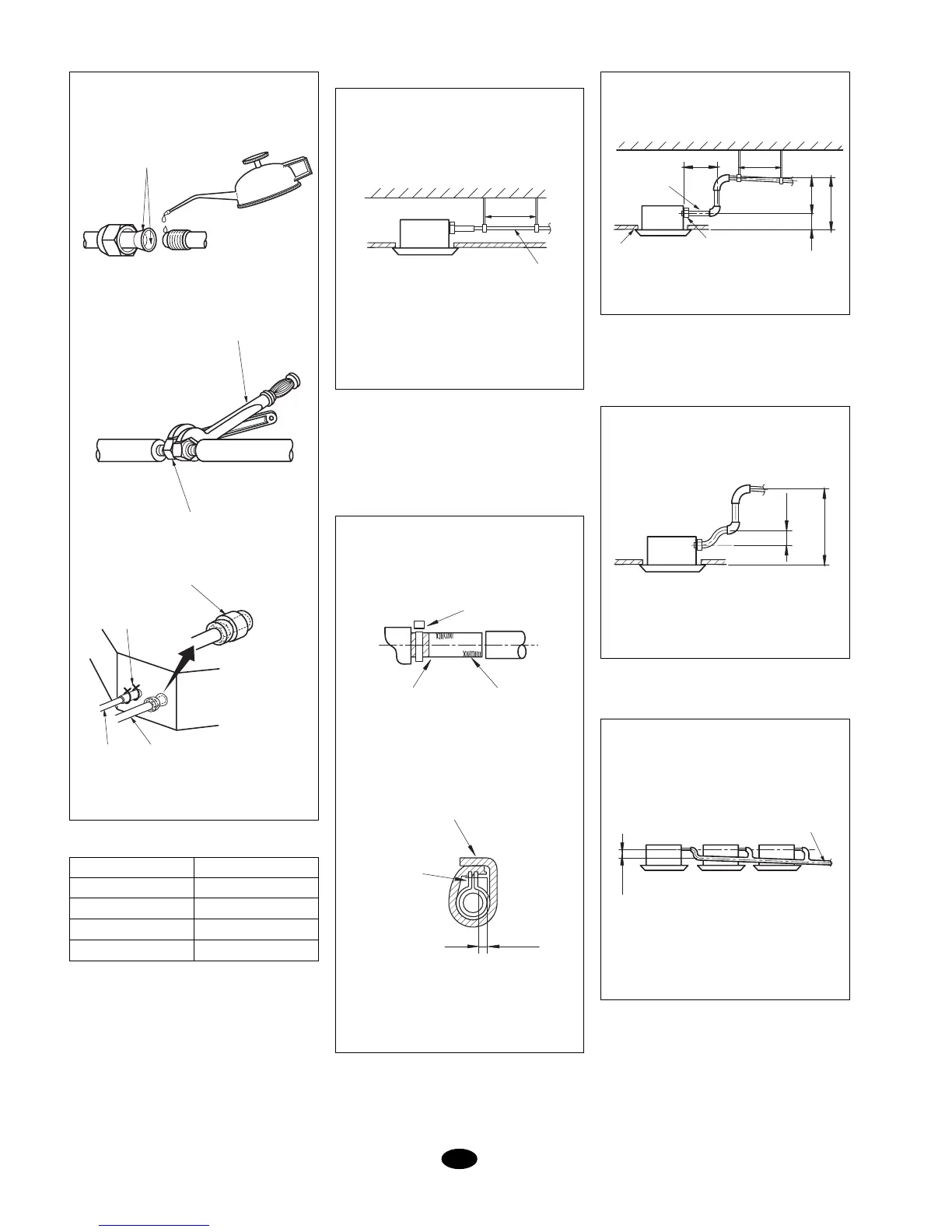
Fig. 5
Diameter
3/8"
1/2"
5/8"
3/4"
Torque
30 to 40 N. m
45 to 50 N. m
60 to 65 N. m
70 to 75 N. m
Fig. 8
Fig. 7
Fig. 6
Fig. 9
Fig. 9 bis
10 m., taking into account there is a maxi-
mum permitted length of 25 metres.
Table 1
Drain hose
(Figs. 6 and 7)
1. Installation of drain hose.
- The diameter of the drain hose should
be greater than, or equal to the dis-
charge pipe (vinyl with a 25 mm. outer
diameter).
- Keep the hose at a slight 1% tilt mini-
mum so as to avoid internal air pockets.
- Should the hose not be inclined suffi-
ciently, add a slight elevation.
- To avoid detachment of the hose, locate
fasteners at at least 1-1.5 m.
- Use hose (1) and clamp (2). Insert hose
over the grey area. Screw on the clamp
until the head protrudes about 4 mm.
- Use the larger insulation to cover the
drain system.
- Insulate the drain inside the room.
Precautions for elevating the
hose (Fig. 8)
- Install elevation at a height of less than
280 mm.
- Install the elevation at at least 300 mm.
from the unit, and with a correct angle.
Attention: (Figs. 9 and 9a)
- The tilt of the hose supplied could be 75
mm. or less, without the hose bearing any
additional stress.
- Follow this advice to install a multiple sys-
tem.
2. Once installation is concluded, make
sure water flows correctly.
- Through the inspection hole, add ap-
proximately 600 cm³ of water to the drain
system. Pour the water slowly and check
flow.
- Once wiring installation is concluded,
check drain flow in cooling mode.
COVER WITH
COOLING OIL
FIXED WRENCH
NUT
INSULATION
FILLING (11)
INSULATION (8)
CLAMP (4) x 4
GASLIQUID
1% SLOPE
1 a 1.5 m
GREY TAPE HOSE (1)
CLAMP (2)
< 4 mm
CLAMP (2)
FILLER (10)