21
GB
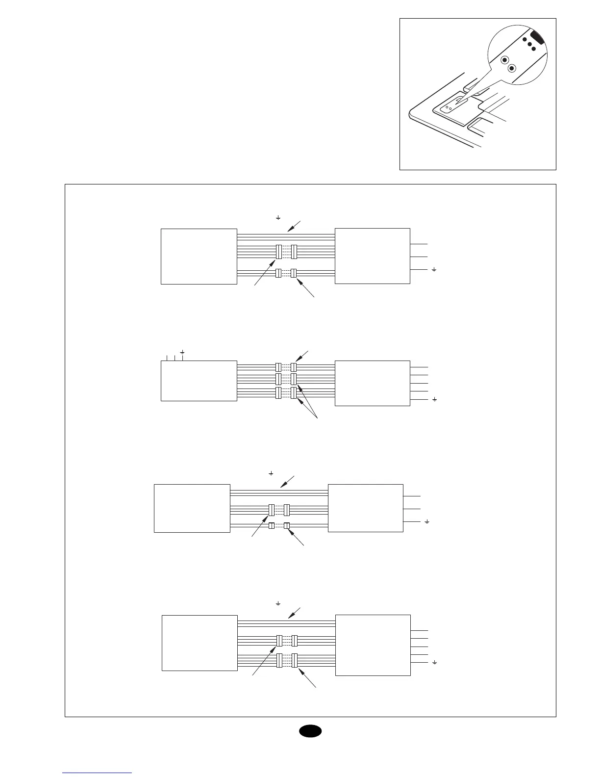
Wiring
Heat pump
Cool only
After installation test and
check operations
Test operation (Fig. 19)
1. Prior to test:
(1)Do not connect the unit until com-
pletely installed.
(2)Wiring should be correct and safe.
(3)Valves should be open.
(4)The unit should be free of impurities.
2. Test operation method:
(1)Connect the unit and press ON/OFF
button on the remote control unit.
(2)Press the MODE button to make sure
all three modes are operative:
COOL, HEAT, DEHUMIDIFICATION.
3. Emergency method.
Whenever the remote control unit can-
not be used, proceed as follows:
* With the unit off, press AUTO to acti-
vate. The unit will operate in the cor-
responding mode.
* With the unit on, press AUTO to turn
it off.
Note: The TEST mode is for testing pur-
poses only. Do not use as a regular operat-
ing mode.
POWER SUPPLY 3 WIRES
(L,N, ) 230V/1Ph/50Hz (SUPPLIED)
DBK 75 AG DBO 75 AG
N
L1
INDOOR UNIT
MANEUVRE CONNECTOR
5 WIRES SUPPLIED
MANEUVRE CONNECTOR
3 WIRES SUPPLIED
OUTDOOR UNIT
3 WIRES
230V/1Ph/50Hz
POWER SUPPLY
230V/1Ph/50Hz
NL
N
L1
L3
L2
INDOOR UNIT
MANEUVRE CONNECTOR
3 WIRES SUPPLIED
MANEUVRE CONNECTOR
4 WIRES SUPPLIED
OUTDOOR UNIT
5 WIRES
400V/3Ph/50Hz
DBK 100 AG
DBK 120 AG
DBO 100 AG
DBO 120 AG
POWER SUPPLY 3 WIRES
(L,N, ) 230V/1Ph/50Hz (SUPPLIED)
DFK 75 AG DFO 75 AG
INDOOR UNIT
MANEUVRE CONNECTOR
4 WIRES SUPPLIED
MANEUVRE CONNECTOR
2 WIRES SUPPLIED
OUTDOOR UNIT
N
L1
3 WIRES
230V/1Ph/50Hz
POWER SUPPLY 3 WIRES
(L,N, ) 230V/1Ph/50Hz (SUPPLIED)
N
L1
L3
L2
INDOOR UNIT
MANEUVRE CONNECTOR
4 WIRES SUPPLIED
MANEUVRE CONNECTOR
5 WIRES SUPPLIED
OUTDOOR UNIT
5 WIRES
400V/3Ph/50Hz
DBK 100 AG
DBK 120 AG
DBO 100 AG
DBO 120 AG
Fig. 19