20
Fig. 16
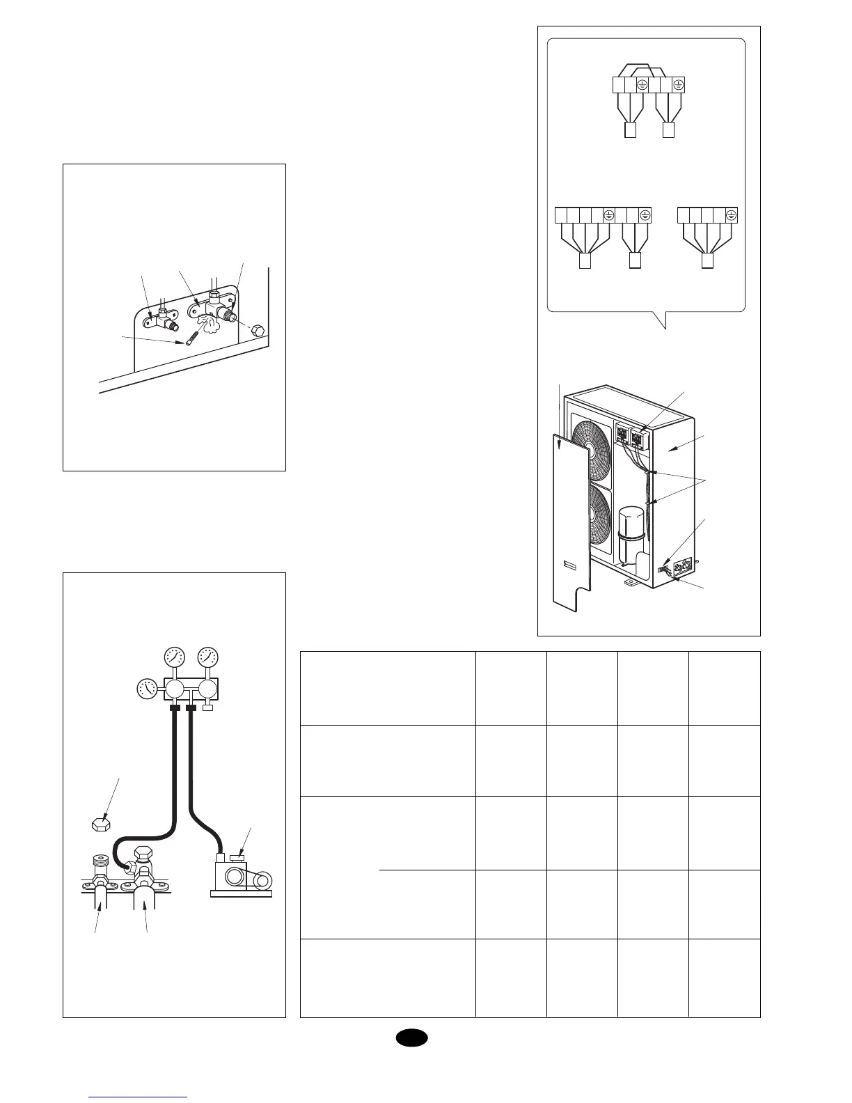
Fig. 17
GB
6. Stop pressing as soon as the refriger-
ant becomes visible, and reinstall the
service port nut.
7. Open both the gas as well as the liquid
valves completely. (Fig. 16)
8. Tighten valve nuts.
9. Check for possible leaks throughout the
circuit, using liquid soap or a leak de-
tector.
Pumping out the circuit
It is quite advisable to pump out the circuit
for correct operation. This eliminates possi-
ble gas and humidity residues from the cir-
cuit. See Fig. 17.
Electrical connection
(1) Read the identification plate carefully.
Carry out connection in accordance with
wiring diagram inside the unit.
(2) Some sort of switch that is capable of
disconnecting the entire unit should be
installed.
(3) Connect the grounding connection.
(4) All wiring should be carried out by quali-
fied personnel and in accordance with
the wiring diagram. Incorrect wiring could
cause a fire hazard or electric dis-
charges.
Connecting power supply
(1) Remove the front cover. (Fig. 18)
(2) Enable cable intake and protect it with a
rubber protection.
(3) Insert all cables through this protection.
(4) Connect the outdoor unit in compliance
with the wiring diagram.
(5) Fasten the cables with the clips and
straps.
Attention:
(1) Ground firmly.
(2) Connect cables firmly.
(3) Do not force connectors.
(4) Power supply connection:
* Cool only units - Connect 3-cable
hose to terminals L, N1 and ground.
- Connect 5-cable hose to terminals
L1, L2, L3, N and ground.
* Cool/heat units - Connect 5-cable
hose to terminals L1, L2, L3, N and
ground.
(5) Connect remaining cables accordingly.
- Do not pull cable when fastening with
the clips and straps.
- Do not leave cable too loose in the
outdoor unit.
PRESSURE
THREAD
LIQUID
VALVE
GAS
VALVE
SERVICE
VALVE
PRESSURE GAUGE
NUT
VACUUM
PUMP
GAS
PIPE
LIQUID
PIPE
Fig. 18
ELECTRICAL
CONNECTION
SIDE COVER
FRONT
COVER
STRAPS
CABLE
INTAKE
CABLES
5 CABLES
POWER
SUPPLY
3 CABLES
INDOOR
UNIT
5 CABLES
POWER
SUPPLY
ELECTRICAL CONNECTION
L1 L2 L3 N L N L1 L2 L3 N
DFO 100, 120 DBO 100, 120
L N L1 N1
DFO, DBO 75
3 CABLES
POWER
SUPPLY
3 CABLES
INDOOR
UNIT
Cable section DFK and DBK
Interconnection
Fuse
3 x 2.5
Power supply
Sizes
DFK, DFO
75
DFK, DFO
100, 120
DBK, DBO
75
DBK, DBO
100, 120
3 x 2.5 5 x 2.5 5 x 2.5
mm
2
Control
mm
2
A
3 x 1.5 3 x 1.5 3 x 1.5 -
6 x 1.5 9 x 1.5 8 x 1.5 11 x 1.5
16 16 10 10
Power
mm
2