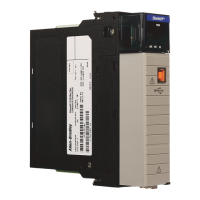
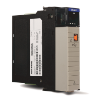
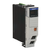
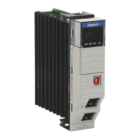
14 Ethernet Network Appliance (with Network Address Translation)
Publication
9300-IN001A-EN-P - December 2012
Attach the Power Connector
Follow these steps to connect the DC power connector:
1. Insert the power connector into the Power receptacle on the bottom
of the unit.
2. Use a screwdriver to tighten the captive screws on the sides of the
power connector.
Connect the Copper Ethernet Ports
Follow these steps to connect the copper Ethernet port(s) on the module.
1. Locate the copper Ethernet RJ-45 ports on the module.
2. Connect one end of an Ethernet cable to one of the copper ports on
the module.
3. Connect the other end of the Ethernet cable to a device in your
Ethernet network.
Grounding Considerations
This product is intended to be mounted to a well-grounded mounting surface
such as a metal panel. The functional earth ground connection to the product
is through the specified pin on the dc connection terminals.
Refer to publication 1770-4.1
, Industrial Automation Wiring and Grounding
Guidelines, for additional information.
You must provide an acceptable grounding path for each device in your
application. For more information on proper grounding guidelines, refer to
publication 1770-4.1
, Industrial Automation Wiring and Grounding Guidelines.

 Loading...


