138 Rockwell Automation Publication 1769-IN088A-EN-P - February 2011
Chapter 3 I/O Memory Mapping
• HI = Hold for initialization: (0 = Disabled, 1 = Enabled)
• PFE = Program/idle to fault enable: (0 = Disabled, 1 = Enabled)
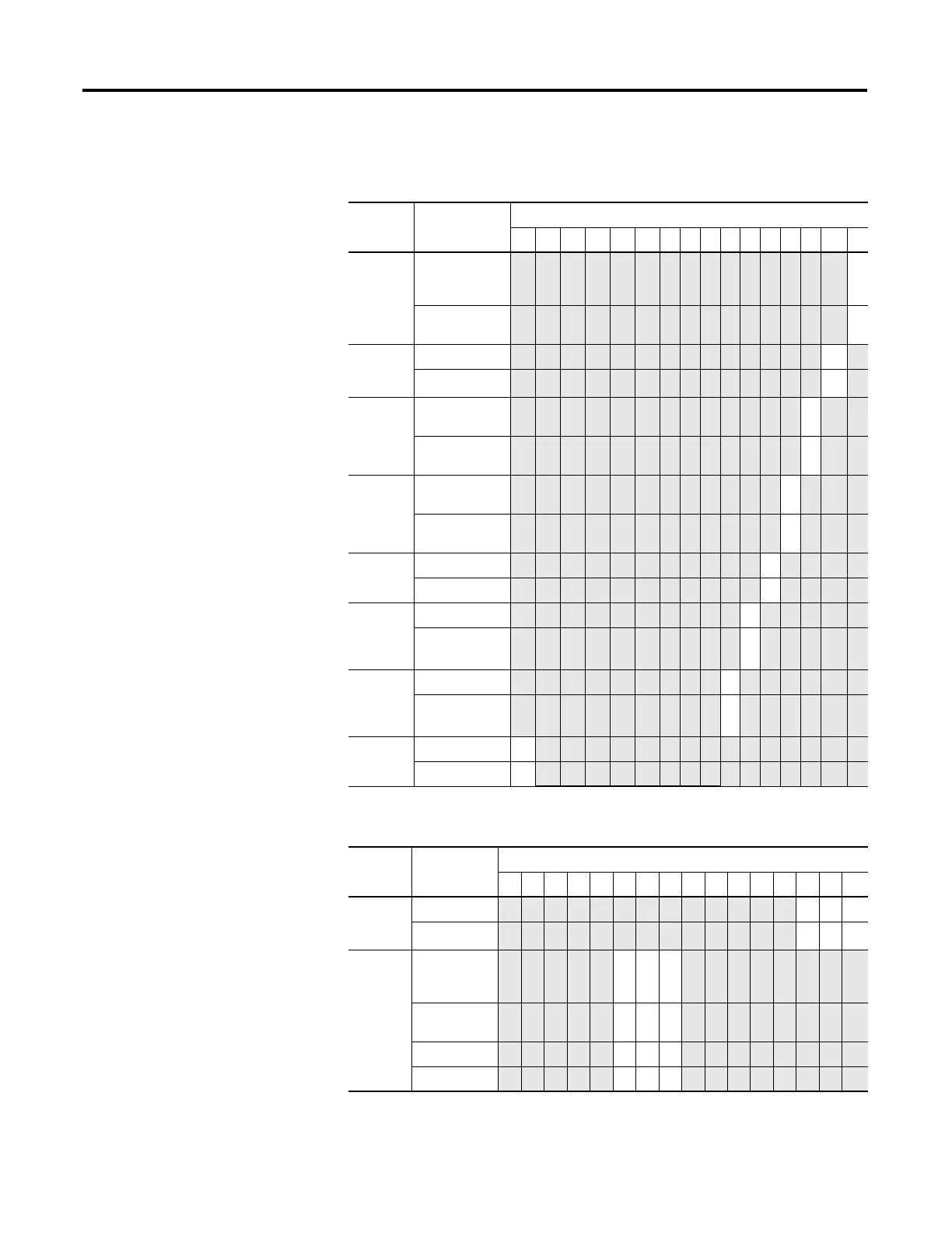
Define Indicate this These bit settings
151413121110987654321 0
Program
(Idle) to
Fault
Enable
Program (Idle)
Mode Data
Applied
(1)
(1) These functions are not supported by all controllers, such as MicroLogix 1500, using any configuration method.
Refer to your controller manual for details.
0
Fault Mode Data
Applied
(1)
1
Hold for
Initializati
on
Disabled 0
Enabled 1
Program
(Idle)
Mode
Hold Last
State
(1)
0
User-Defined
Value
(1)
1
Fault
Mode
Hold Last
State
(1)
0
User-Defined
Fault Value
(1)
1
Enable
Ramping
Disabled 0
Enabled 1
System
Interrupt
High
Clamp
Disabled 0
Enabled
(1)
1
System
Interrupt
Low
Clamp
Disabled 0
Enabled
(1)
1
Enable
Channel
Disabled 0
Enabled 1
Define Indicate this These bit settings
1514131211109876543210
Output
Range
Select
0…20 mA DC
000
4…20 mA DC
001
Output
Data
Select
Raw/
Proportional
Counts
0 0 0
Engineering
Units
001
Scaled for PID 010
Percent Range 011

 Loading...


