Rockwell Automation Publication 1769-IN088A-EN-P - February 2011 71
I/O Memory Mapping Chapter 3
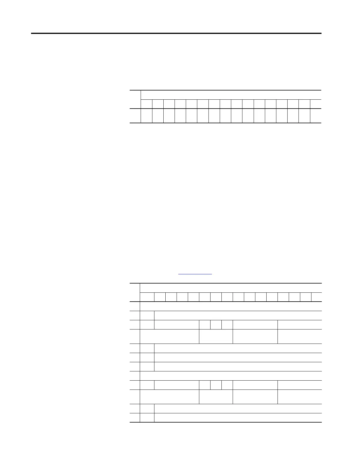
Output Data File
For each input module, slot x, word 0 in the output data file contains alarm
unlatch control bits.
The bits are defined as follows:
• CLHx = Cancel High Process Alarm Latch for Input x. Allows each input
high-process-alarm latch to be individually cancelled. Cancel = 1.
• CLLx = Cancel Low Process Alarm Latch for Input x. Allows each input
low-process-alarm latch to be individually cancelled. Cancel = 1.
Configuration Data File
The manipulation of the bits from this file is normally done with programming
software, such as RSLogix 500, RSLogix 5000, or RSNetWorx for DeviceNet,
during initial configuration of the system. In that case, graphical screens are
provided by the programmer to simplify configuration. However, some systems,
like the 1769-ADN DeviceNet adapter, also allow the bits to be altered as part of
the control program, using communication rungs. In that case, it is necessary to
understand the bit arrangement. Refer to the Compact Analog I/O User Manual,
publication number 1769-UM002
for additional details.
Word
Bit Position
1514131211109876543210
0CL
L7
CL
H7
CL
L6
CL
H6
CL
L5
CL
H5
CL
L4
CL
H4
CL
L3
CL
H3
CL
L2
CL
H2
CL
L1
CL
H1
CL
L0
CL
H0
Word
Bit Position
15 14131211109876543210
0 Real Time Sample Value
1 ERTS Reserved
2 EC Reserved EA AL EI Reserved Input Filter Sel Chl0
3 Reserved Inpt Dta Fm
Chl0
Reserved Inpt Tp/RngeSel Chl0
4 S Process Alarm High Data Value Channel 0
5 S Process Alarm Low Data Value Channel 0
6 S Alarm Dead Band Value Channel 0
7Pad
8 EC Reserved EA AL EI Reserved Inpt Filter Sel Chl1
9 Reserved Inpt Dta Fm
Chl1
Reserved Inpt Tp/RngeSel Chl1
10 S Process Alarm High Data Value Channel 1
11 S Process Alarm Low Data Value Channel 1

 Loading...


