70 Rockwell Automation Publication 1769-IN088A-EN-P - February 2011
Chapter 3 I/O Memory Mapping
1769-IF8
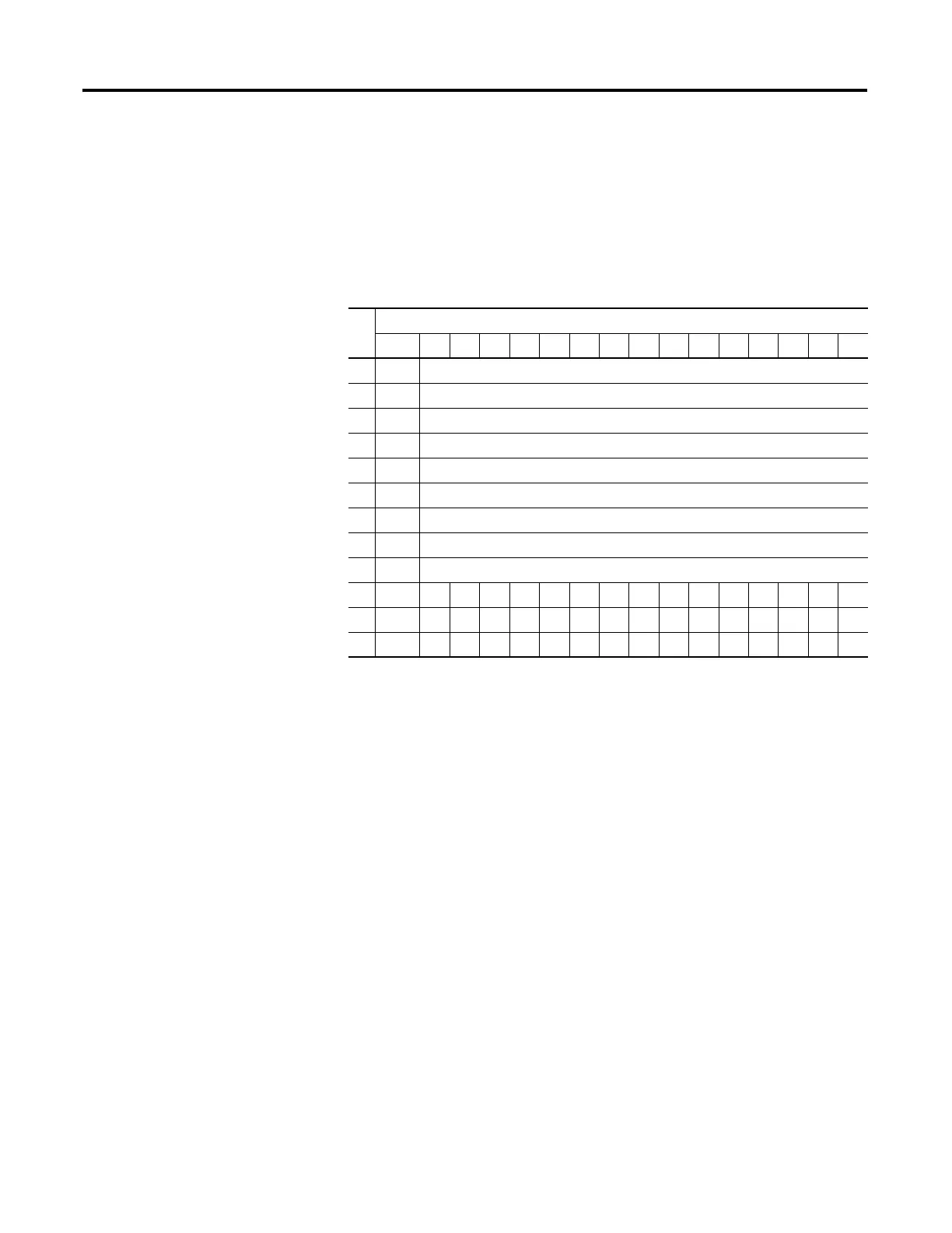
The following I/O memory mapping lets you configure the 1769-IF8 module.
Input Data File
For each input module, slot x, words 0…7 in the input data file contain the analog
values of the inputs.
The bits are defined as follows:
• SGN = Sign bit in two’s complement format.
• Nu = Not used. Bit set to 0.
• Sx = General status bit for input channels 0…7.
• Lx = Low alarm flag bits for input channels 0…7.
• Hx = High alarm flag bits for input channels 0…7.
• Ux = Under-range flag bits for channels 0…7. When set, the input signal is
under normal range or an open circuit condition exists, in the case of the
4-20mA range.
• Ox = Over-range flag bits for channels 0…7.
Word
Bit Position
15 14131211109876543210
0 SGN Analog Input Data Channel 0
1 SGN Analog Input Data Channel 1
2 SGN Analog Input Data Channel 2
3 SGN Analog Input Data Channel 3
4 SGN Analog Input Data Channel 4
5 SGN Analog Input Data Channel 5
6 SGN Analog Input Data Channel 6
7 SGN Analog Input Data Channel 7
8 Nu Time Stamp Value
9 Nu NuNuNuNuNuNuNuS7S6S5S4S3S2S1S0
10 L3 H3 U3 O3 L2 H2 U2 O2 L1 H1 U1 O1 L0 H0 U0 O0
11 L7 H7 U7 O7 L6 H6 U6 O6 L5 H5 U5 O5 L4 H4 U4 O4

 Loading...


