92 Rockwell Automation Publication 1769-IN088A-EN-P - February 2011
Chapter 3 I/O Memory Mapping
1769-IG16
The following I/O memory mapping lets you configure the 1769-IG16 module.
Input Data File
For each module, slot x, word 0 in the input data file contains the state of the
module’s input points. The module implements inverted logic on the TTL
inputs. A logix low-input voltage results in the corresponding Input Data File bit
being set to 1. A logic high-input voltage results in the corresponding bit being
cleared to 0.
Enable
Channel
Enable 1
Disable 0
Input
Range
Select
-10…+10V 0000
0…5V 0001
0…10V 0010
1…5V
0011
Input Data
Format
Select
Proportional
Counts
000
Engineering
Units
001
Scaled for
PID
010
Percent
Range
011
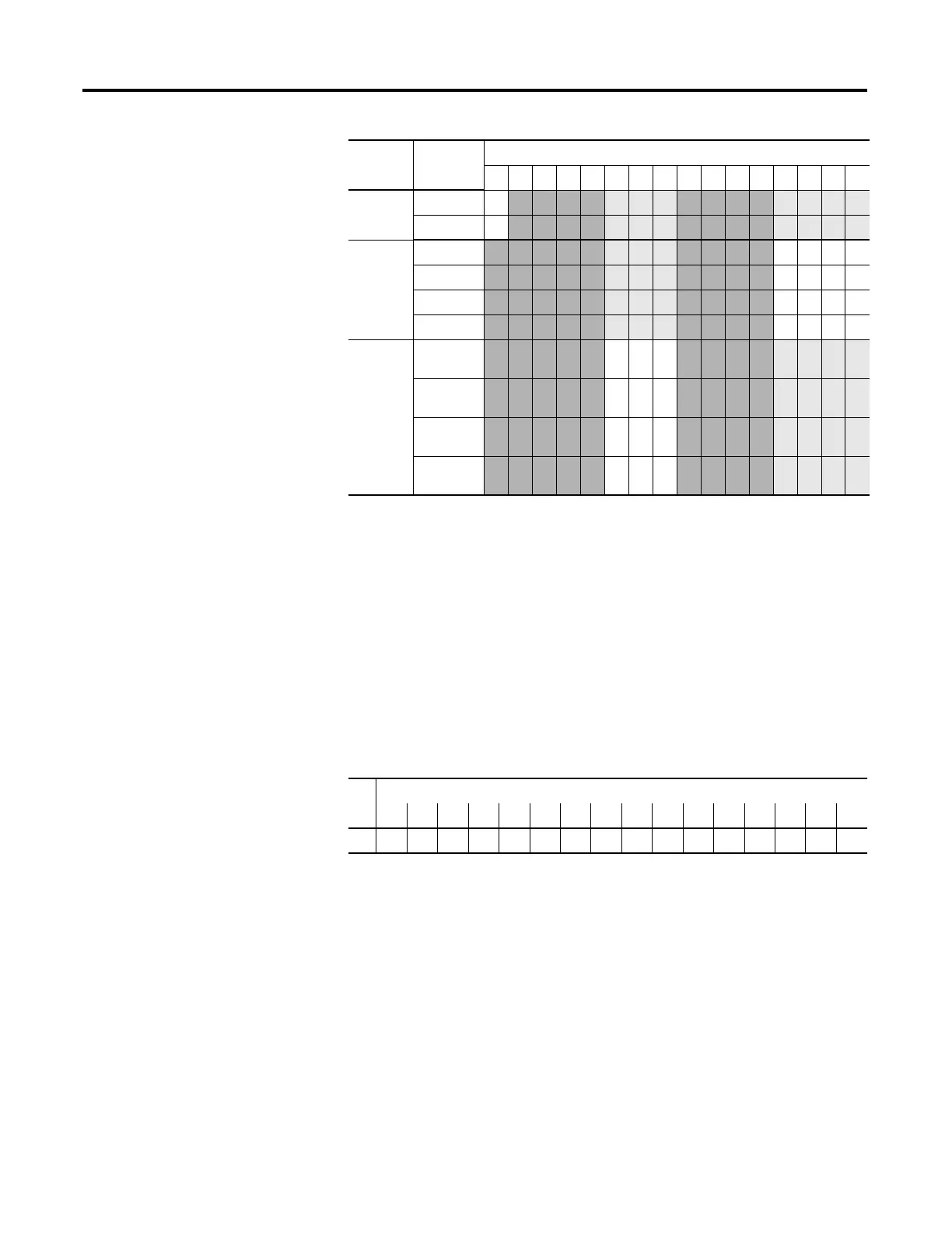
Define To Choose Make these bit settings
15 14 13 12 11 10 09 08 07 06 05 04 03 02 01 00
Word
Bit Position
1514131211109876543210
0r
(1)
(1) r = read.
rrrrrrrrrrrrrrr

 Loading...


