180 Rockwell Automation Publication 1769-IN088A-EN-P - February 2011
Chapter 3 I/O Memory Mapping
1769-ASCII
The 1769-ASCII module supports an input assembly that is accessible through
the Assembly Object (Class 4), Instance 101. The input assembly is up to 108
words. The module supports an output assembly that is accessible through the
Assembly Object (Class 4), Instance 100. The output assembly is up to 108
words.
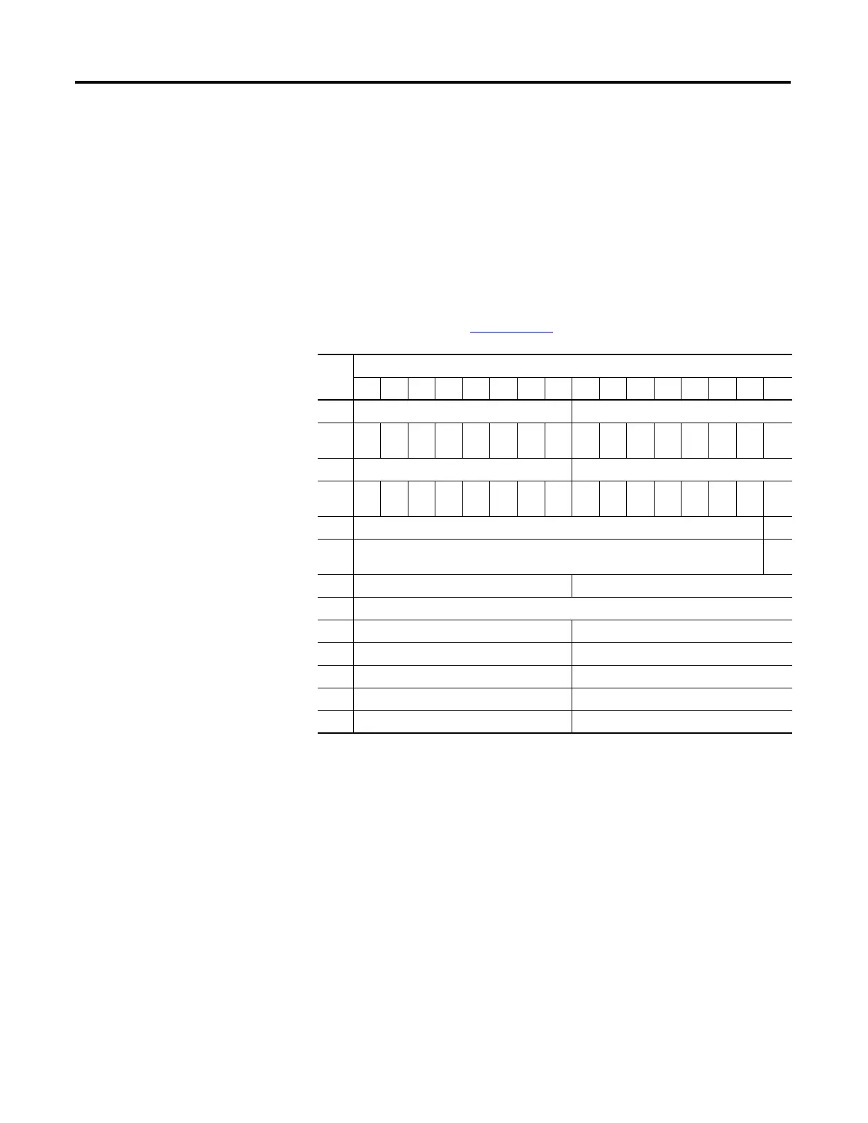
Alternate Mode (One Channel at a Time) Input File
Maximum size is shown below. Refer to the Compact I/O 1769-ASCII Module
User Manual, publication 1769-UM012
, to use smaller input files.
The bits are defined as follows:
• Tx = Transmit.
• Rx = Receive.
• TS = Transmit sent. Indicates the ASCII module has sent the data
indicated by the Tx Transaction ID and can accept more transmit data.
• ND = New data. Only used for Handshake mode.
• HE = Handshake error. Only used for Handshake mode.
Word
Bit Position
1514131211109876543210
0 Tx ID 0 Acknowledged Rx Transaction ID Ch0
1 151413121110TG
0
TS
0
ND
0
HE
0
NR
0
RF
0
TF
0
PA
0
RO
0
TO
0
2 Tx ID 1 Acknowledged Rx Transaction ID Ch1
3 151413121110TG
1
TS
1
ND
1
HE
1
NR
1
RF
1
TF
1
PA
1
RO
1
TO
1
4Reserved CNI
5Reserved CN
O
6 Firmware Revision, Major Firmware Revision, Minor
7 Length (Number of Bytes)
8 Character 1 Character 0
9 Character 3 Character 2
… Character … Character …
106 Character 197 Character 196
107 Character 199 Character 198

 Loading...


