14 Rockwell Automation Publication 1769-IN088A-EN-P - February 2011
Chapter 1 Install a 1769 Module
System Assembly
The module can be attached to the controller or an adjacent I/O module before
or after mounting.
• For mounting instructions, see Panel Mounting
on page 15 or DIN Rail
Mounting on page 16.
• To work with a system that is already mounted, see Replace a Module
on
page 17.
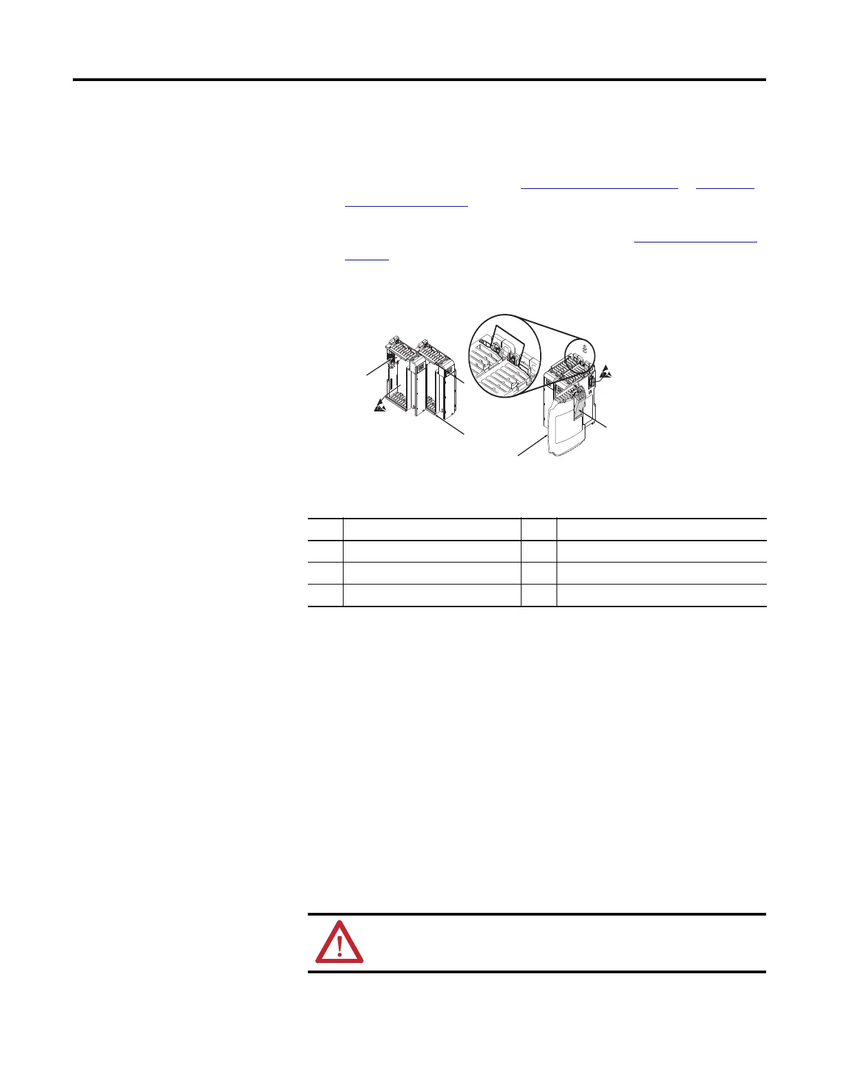
The following procedure shows you how to assemble the Compact I/O system.
1. Disconnect power.
2. Check that the bus lever of the module to be installed is in the unlocked
(fully right) position.
3. Use the upper and lower tongue-and-groove slots (1) to secure the modules
together (or to a controller).
4. Move the module back along the tongue-and-groove slots until the bus
connectors (2) line up with each other.
5. Push the bus lever back slightly to clear the positioning tab (3).
Use your fingers or a small screwdriver.
6. To allow communication between the controller and module, move the
bus lever fully to the left (4) until it clicks.
7. Make sure the lever is locked firmly in place.
Item Description Item Description
1 Tongue-and-groove slots 4 Bus lever
2 Bus connectors 5 End-cap terminator
3 Positioning tab 6 End-cap bus terminator
ATTENTION: When attaching I/O modules, it is very important that the
bus connectors are securely locked together to make a proper electrical
connection.
6
5
4
3
1
1
2

 Loading...


