Rockwell Automation Publication 1769-IN088A-EN-P - February 2011 143
I/O Memory Mapping Chapter 3
The bits are defined as follows:
• PF = Analog power fail.
• S = General status (over-range, under-range, or open-circuit).
• D = Open-circuit diagnostics.
• H = Output held bit.
• U = Under-range (or low-clamp exceeded) alarm.
• O = Over-range (or high-clamp exceeded) alarm.
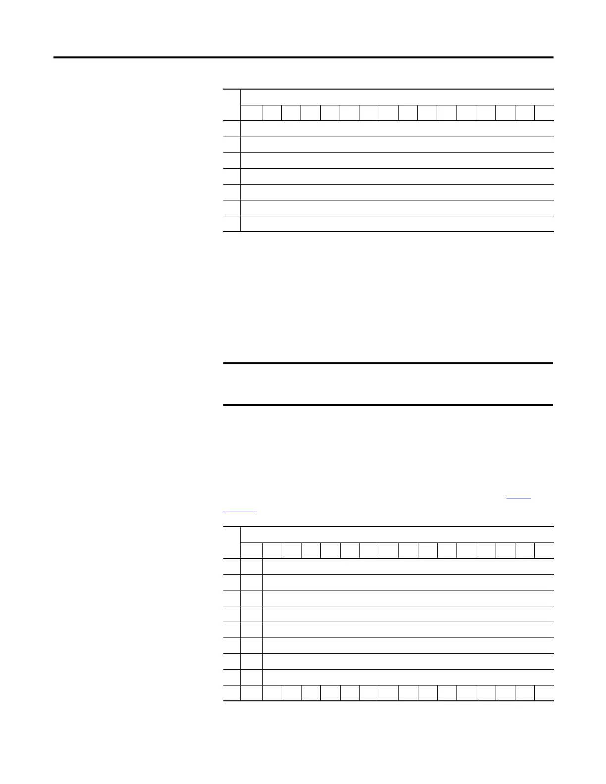
Output Data File
For each module, slot x, words 0…7 in the output data file contain the channel
0…7 output data. Word 8 is used to unlatch any condition that has been latched.
Refer to the Compact Analog I/O User Manual, publication number 1769-
UM002 for additional details.
4 Channel 1 Data Value
5 Channel 2 Data Value
6 Channel 3 Data Value
7 Channel 4 Data Value
8 Channel 5 Data Value
9 Channel 6 Data Value
10 Channel 7 Data Value
The output module’s input data file reflects the analog output data echo
of the module, not necessarily the electrical state of the output
terminals. It does not reflect shorted or open outputs.
Word
Bit Position
1514131211109876543210
0 SGN Analog Output Data Channel 0
1 SGN Analog Output Data Channel 1
2 SGN Analog Output Data Channel 2
3 SGN Analog Output Data Channel 3
4 SGN Analog Output Data Channel 4
5 SGN Analog Output Data Channel 5
6 SGN Analog Output Data Channel 6
7 SGN Analog Output Data Channel 7
8 UU7 UO7 UU6 UO6 UU5 UO5 UU4 UO4 UU3 UO3 UU2 UO2 UU1 UO1 UU0 UO0
Word
Bit Position
1514131211109876543210

 Loading...


