EasyManuals Logo

Rockwell Automation Allen-Bradley 1769-OF4 Installation Instructions

Rockwell Automation Allen-Bradley 1769-OF4
202 pages
To Next Page IconTo Next Page
To Previous Page IconTo Previous Page
Page #35 background imageLoading...
Page #35 background image
Rockwell Automation Publication 1769-IN088A-EN-P - February 2011 35
Module Wiring Chapter 2
EXC 3
SENSE 3
RTN 3
EXC 3
SENSE 3
RTN 3
EXC 3
SENSE 3
RTN 3
EXC 3
SENSE 3
RTN 3
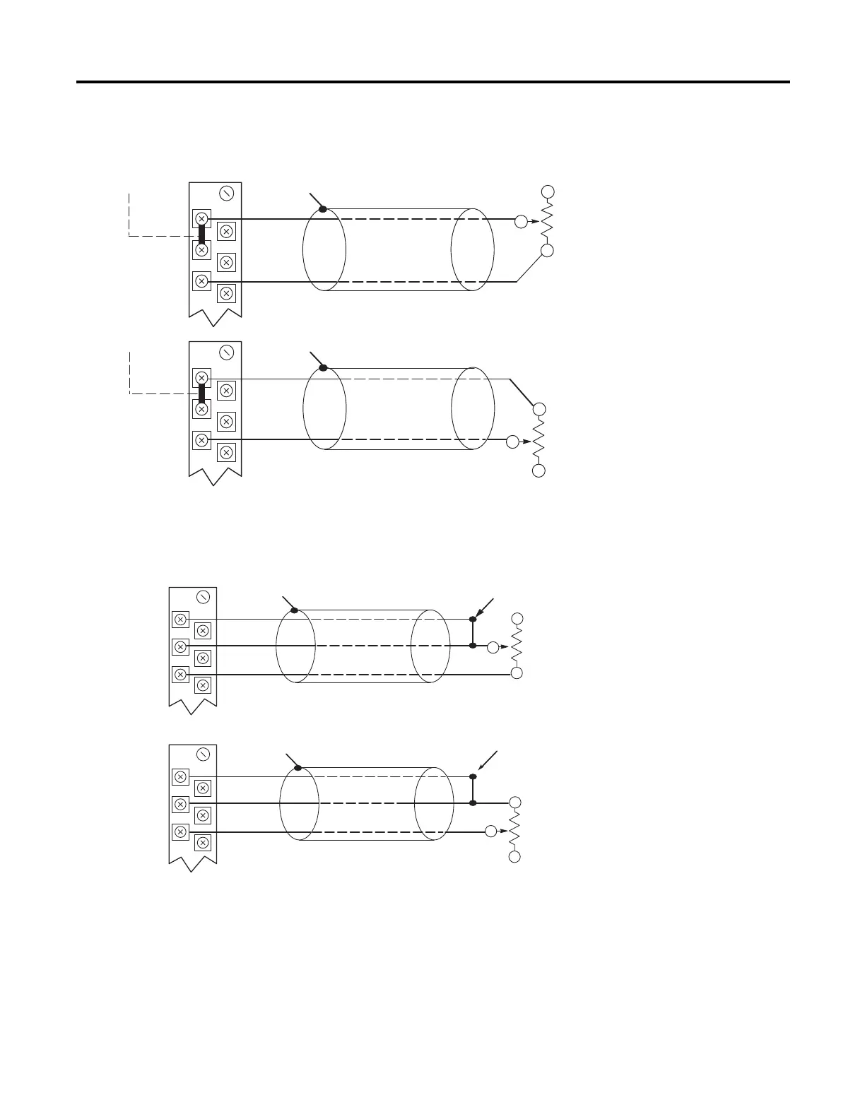
Two-wire Potentiometer Configuration
Three-wire Potentiometer Configuration
Add Jumper
Cable Shield (to Ground)
Return
RTD EXC
Belden 9501 Shielded Cable
Run RTD EXC and sense wires from the module to
potentiometer terminal and tie terminal to one point.
Sense
RTD EXC
Belden 83503 or 9533 Shielded Cable
Return
Potentiometer
Potentiometer
Return
RTD EXC
Belden 9501 Shielded Cable
Cable Shield (to Ground)
Add Jumper
Potentiometer
Potentiometer
Belden 83503 or 9533 Shielded Cable
Sense
RTD EXC
Return
Cable Shield (to Ground)
Run RTD EXC and sense wires from the module to
potentiometer terminal and tie terminal to one point.

Table of Contents

Other manuals for Rockwell Automation Allen-Bradley 1769-OF4

Questions and Answers:

Question and Answer IconNeed help?

Do you have a question about the Rockwell Automation Allen-Bradley 1769-OF4 and is the answer not in the manual?

Rockwell Automation Allen-Bradley 1769-OF4 Specifications

General IconGeneral
BrandRockwell Automation
ModelAllen-Bradley 1769-OF4
CategoryControl Unit
LanguageEnglish

Related product manuals