Rockwell Automation Publication 1769-IN088A-EN-P - February 2011 73
I/O Memory Mapping Chapter 3
The bits are defined as follows:
• EC = Enable Channel
• Inpt Dta Fm Chlx = Input Data Format Select.
• EA = Enable Alarm.
• AL = Alarm Latch.
• EI = Enable Interrupt.
• Inpt Tp/Rnge Sel Chlx = Input Type/Range Select.
• Inpt Filter Sel Chlx = Input Filter Select.
• Reserved = Allows for future expansion.
• ERTS = Enable Real Time Sample.
47 S Process Alarm Low Data Value Channel 7
48 S Alarm Dead Band Value Channel 7
49 Pad
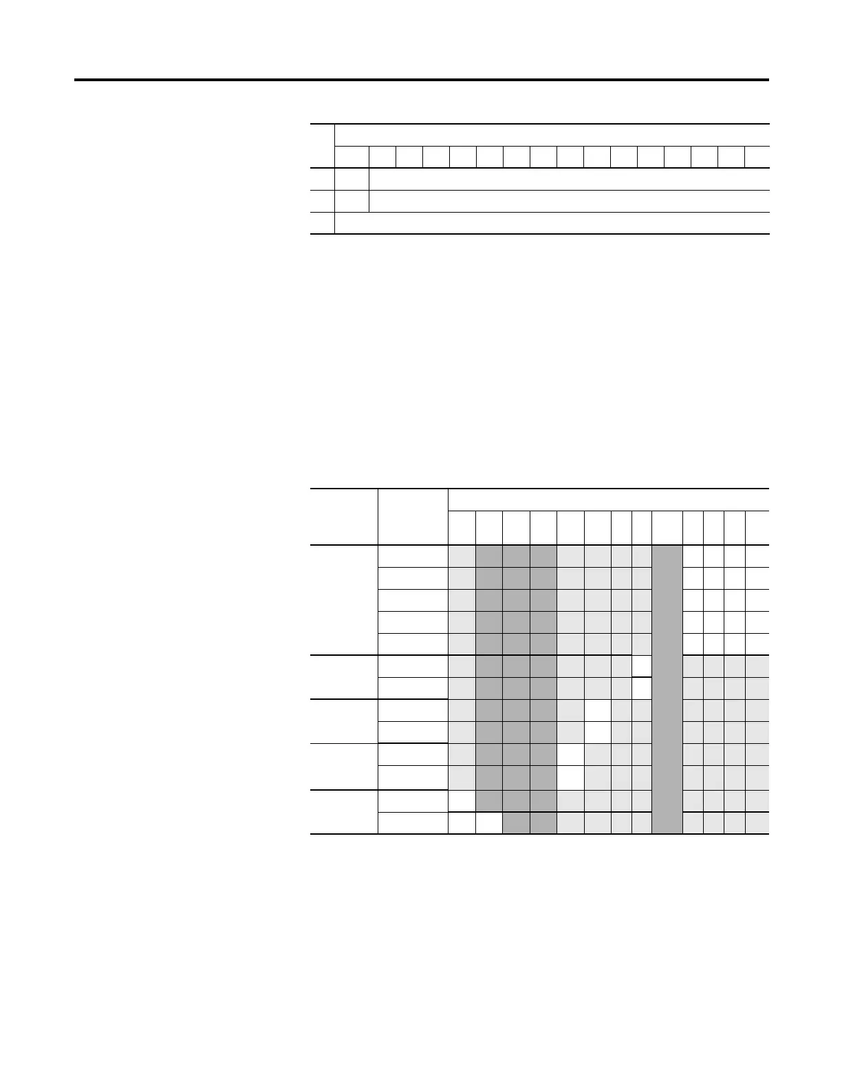
Define To Select Make these bit settings
15 14 13 12 11 10 9 8 7…
4
3210
Input Filter
Selection/
-3 dB
Frequency
60 Hz
0000
50 Hz
0001
10 Hz 0010
250 Hz 0011
500 Hz
0100
Enable
Interrupt
Enable 1
Disable 0
Process
Alarm Latch
Enable 1
Disable 0
Enable
Process
Alarms
Enable 1
Disable 0
Enable
Channel
Enable 1
Disable 0
Word
Bit Position
15 14131211109876543210

 Loading...


