12 Rockwell Automation Publication 5094-IN009C-EN-P - May 2022
FLEX 5000 High-speed Counter I/O Modules Installation Instructions
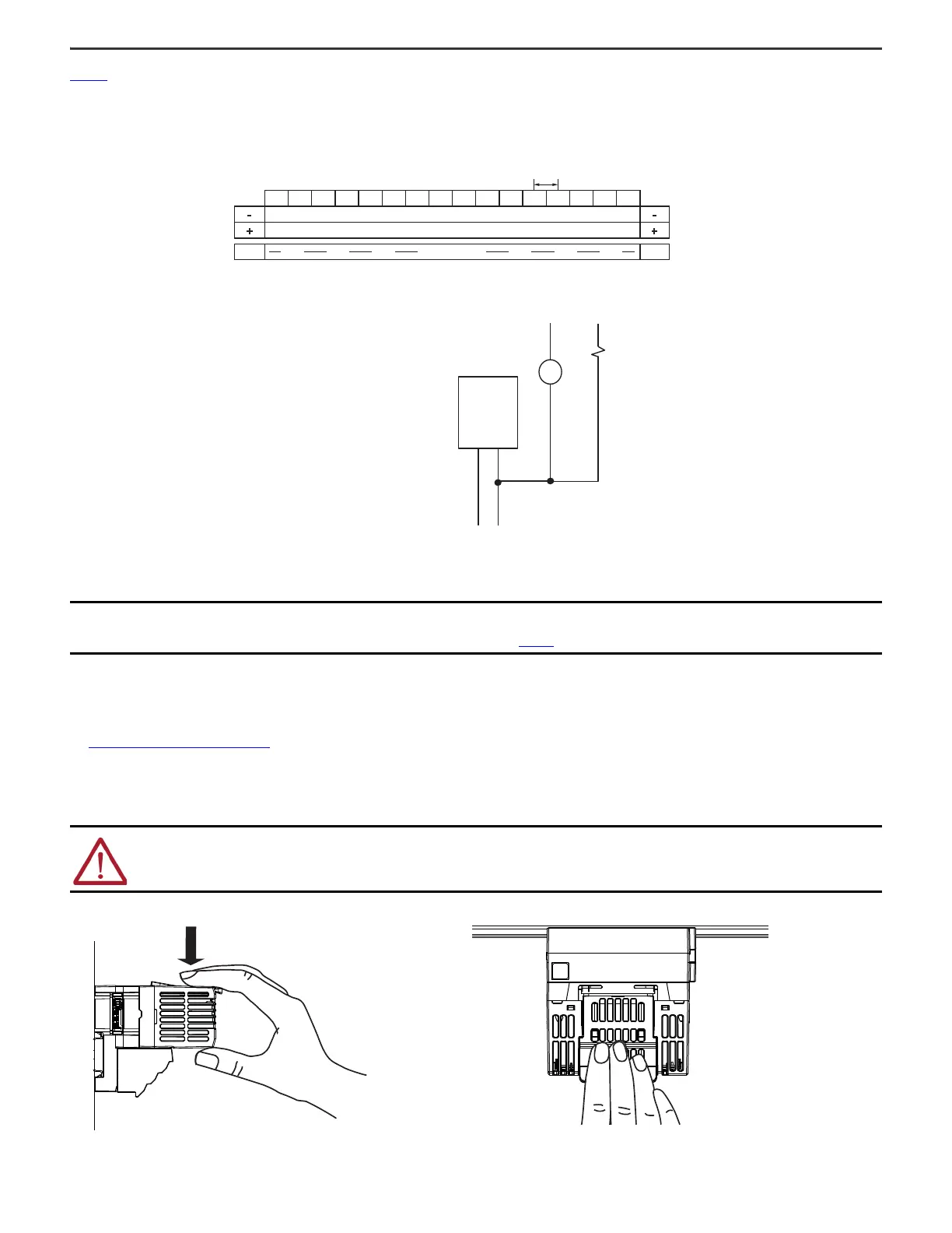
Figure 4 shows a wiring diagram for the 5094-HSC and 5094-HSCXT modules connected to a discrete output device. The 5094-HSC and the 5094-HSCXT modules must be used with
the 5094-STB shield bar accessory.
Figure 4 - 5094-HSC and 5094-HSCXT Wiring Diagram - Discrete Output Device
Power the System
After you install all FLEX 5000 I/O modules, you can turn on power to the FLEX 5000 EtherNet/IP adapter and, if used, field-side power to the terminal bases. For more information,
see System Power Considerations on page 6.
Remove the Module
1. Press and hold the release lever on the top of the module. Be sure to press the entire lever evenly.
2. Pull the module off the terminal base.
IMPORTANT Recommended Surge Suppression – The module has built-in suppression that is sufficient for most applications. For high-noise applications, we
recommend that you use a 1N4004 diode reverse-wired across the load for transistor outputs switching 24V DC inductive loads. For additional details,
see the Industrial Automation Wiring and Grounding Guidelines, publication 1770-4.1
.
WARNING: When you insert or remove the module while backplane power or SA power (field-side) is on, an electric arc can occur. This could cause an explosion
in hazardous location installations.
Be sure that power is removed or the area is nonhazardous before proceeding. Repeated electric arcing causes excessive wear to contacts on both the module
and its mating connector. Worn contacts may create electrical resistance that can affect module operation
Connections to the SA Power RTB on the FLEX 5000 EtherNet/IP adapter
or a 5094-FPD field potential distributor
Input A0+
Input A0-
Input B0+
Input B0-
Input Z0+
Input Z0-
Input A1+
Input A1-
Input B1+
Input B1-
Input Z1+
Input Z1-
Output 0
Output 1
Output 2
Output 3
A0+ A0- B0+ B0- Z0+ Z0- A1+ A1- B1+ B1- Z1+ Z1- O0
3 mm
O1 O2 O3
Common
Voltage
Shield bar
Power
supply
+V DC COM
C
TB3 Terminal Base with 5094-STB shield bar accessory
Shield bar accessory

 Loading...


