Rockwell Automation Publication 5094-IN009C-EN-P - May 2022 7
FLEX 5000 High-speed Counter I/O Modules Installation Instructions
Install the End Cap
An end cap is shipped with a FLEX 5000 EtherNet/IP adapter.
You must install an end cap on the right side of the last terminal base in a FLEX 5000 I/O system. The end cap covers the exposed interconnections on the adapter module or on the
last terminal base in the system. If you do not install the end cap before powering the system, equipment damage or injury from electric shock can result.
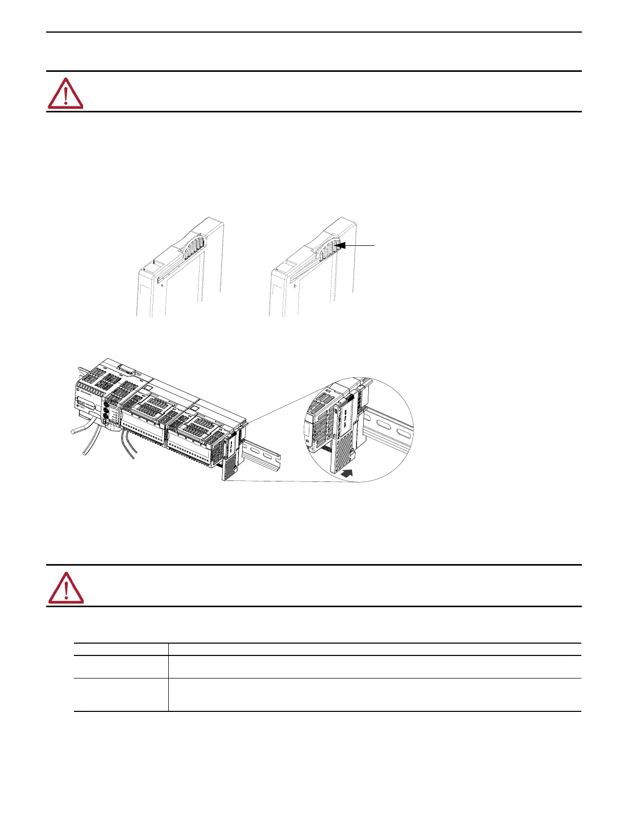
Once you have installed all your modules for your system, install the end cap on the last terminal base.
1. Make sure that the end cap is unlocked.
If the end cap is locked, pull out the tab until it clicks.
2. Align the end cap with interlocking pieces on the last terminal base in the system.
3. Slide the end cap toward the DIN rail.
4. Press the Locking tab until it clicks.
Wire the Terminal Base
1. Confirm that all sources of power to the module and terminal base are turned off.
2. Strip insulation from the wires that you connect to the terminal base.
ATTENTION: Do not discard the end cap. Use this end cap to cover the exposed interconnections on the last mounting base on the DIN rail. Failure to do so
could result in equipment damage or injury from electric shock.
WARNING: If you connect or disconnect wiring while the field-side power is on, an electrical arc can occur. This could cause an explosion in hazardous location
installations. Be sure that power is removed or the area is nonhazardous before proceeding.
TB Type Action
Screw
0.34…2.5 mm
2
(22…14 AWG) = Strip 12 mm ± 1 mm (0.47 in. ± 0.04 in.) of insulation from the wires
Other = Strip 12 mm ± 1 mm (0.47 in. ± 0.04 in.) of insulation from the wires
Spring
0.34….3 mm
2
(22…16 AWG) = Strip 10 mm ± 1 mm (0.39 in. ± 0.04 in.) of insulation from the wires
2.5 mm
2
(14 AWG) = Strip 15 mm ± 1 mm (0.59 in. ± 0.04 in.) of insulation from the wires
Other = Strip 10 mm ± 1 mm (0.39 in. ± 0.04 in.) of insulation from the wires

 Loading...


