6 Rockwell Automation Publication 5094-IN009C-EN-P - May 2022
FLEX 5000 High-speed Counter I/O Modules Installation Instructions
Ground Considerations
You must ground DIN rails according to the Industrial Automation Wiring and Grounding Guidelines, publication 1770-4.1.
You can use a zinc-plated yellow-chromate steel DIN rail such as the Allen-Bradley 199-DR1; 46277-3; EN50022 – 35 x 7.5 mm (1.38 x 0.30 in.) with your FLEX 5000 I/O system.
System Power Considerations
FLEX 5000 EtherNet/IP adapters provide power to a FLEX 5000 I/O system via a Power RTB that is connected to an external power supply and installed on the adapter.
The Power RTB provides module power to the system. Module power refers to system-side power that is used to operate the FLEX 5000 I/O system. Module power is provided
through the Power RTB and passed across the module power bus.
• You must limit the SA field-side power source to 10 A, max, at 18…32V DC.
• Confirm that the external module power supply is adequately sized for the total module power bus current draw in the system.
For example, if the total module power current draw, including current inrush requirements, is 5 A, you can use a module power supply that is limited to 5 A.
• You must use SELV-listed power supplies for module power if there are Functional Safety modules that are connected to the FLEX 5000 I/O system.
• Not all power supplies are certified for use in all applications, for example, nonhazardous and hazardous environments.
For more information, see the publications that are listed in Additional Resources
on page 13.
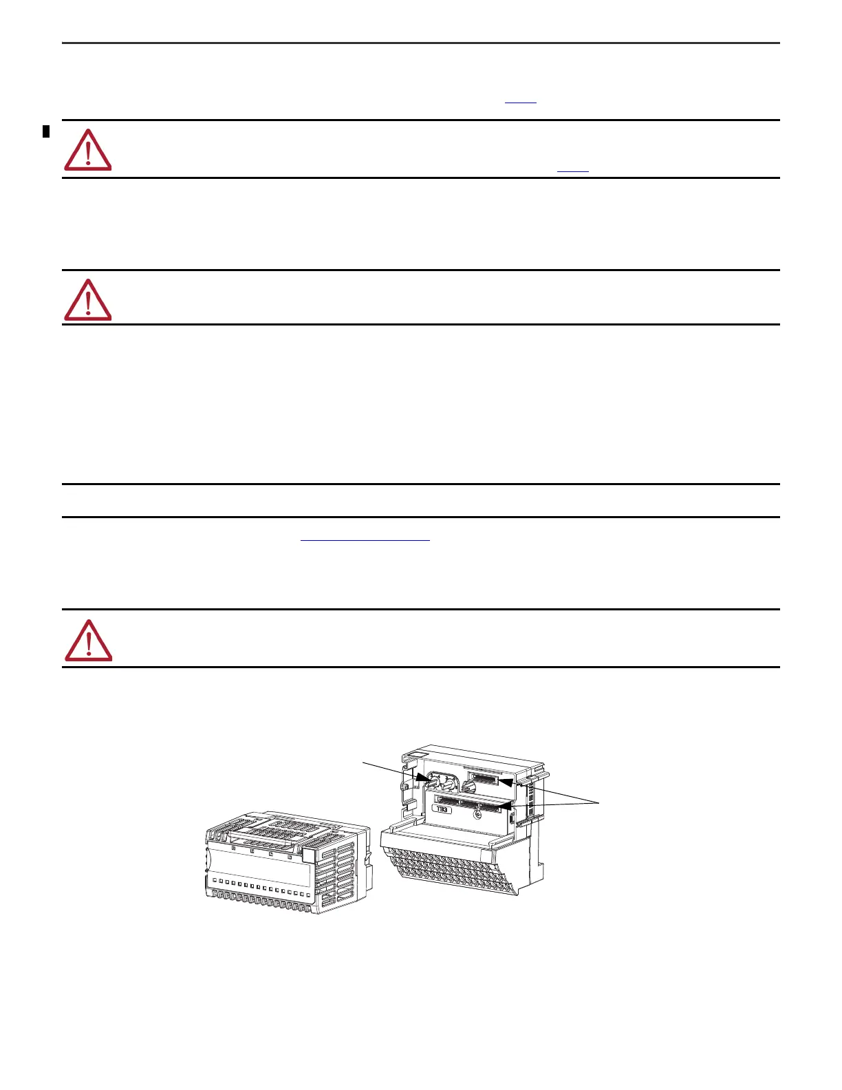
Install the Module
The module mounts on a FLEX 5000 terminal base.
1. Rotate the left keyswitch on the terminal base clockwise to position 4, and the right keyswitch to position 1, as indicated on the module.
2. Position the module in front of the terminal base and make sure the pins are aligned with the connectors in the terminal base.
3. Press firmly and evenly to seat the module on the terminal base. The module is seated when the latching hooks are locked into the terminal base.
ATTENTION: This product is grounded through the DIN rail to chassis ground. Use zinc-plated chromate-passivated steel DIN rail to assure proper grounding.
The use of other DIN rail materials (for example, aluminum or plastic) that can corrode, oxidize, or are poor conductors, can result in improper or intermittent
grounding. Secure DIN rail to mounting surface approximately every 200 mm (7.8 in.) and use end-anchors appropriately. Be sure to ground the DIN rail
properly. See the Industrial Automation Wiring and Grounding Guidelines, Rockwell Automation publication 1770-4.1 for more information.
ATTENTION: Power to this equipment and all connected I/O must be supplied from a source compliant with the following:
Isolated from Mains power via an approved Isolating Transformer constructed with Basic Insulation.
IMPORTANT We recommend that you use separate external power supplies for the adapter and the adjacent terminal base. This practice can prevent unintended
consequences that can result if you use one supply.
WARNING: When you insert or remove the module while backplane power or SA power (field-side) is on, an electric arc can occur. This could cause an explosion
in hazardous location installations.
Be sure that power is removed or the area is nonhazardous before proceeding. Repeated electric arcing causes excessive wear to contacts on both the module
and its mating connector. Worn contacts may create electrical resistance that can affect module operation.

 Loading...


