8 Rockwell Automation Publication 5094-IN009C-EN-P - May 2022
FLEX 5000 High-speed Counter I/O Modules Installation Instructions
3. Connect the wires to the terminal base.
4. Connect individual input wiring to terminals 0…15 as indicated in Wiring Connections for 5094-HSC and 5049-HSCXT on page 9.
5. Connect the associated +V DC power lead of the input device to the corresponding Voltage terminal for each input. (Voltage terminals are internally connected together).
6. Connect the associated input common (3-wire devices only) to the corresponding Common terminal for each input. (Common terminals are internally connected together).
7. Connect +V DC power to terminal SA+ on the left side of the terminal base.
8. Connect V DC common to terminal SA– on the left side of the terminal base.
9. If daisychaining +V DC power to the next terminal base, connect a jumper from terminal SA+ on the right side of this terminal base to terminal SA+ on the left side of the next
terminal base.
10. If continuing V DC common to the next terminal base, connect a jumper from terminal SA– on the right side of this terminal base to terminal SA– on the left side of the next
terminal base.
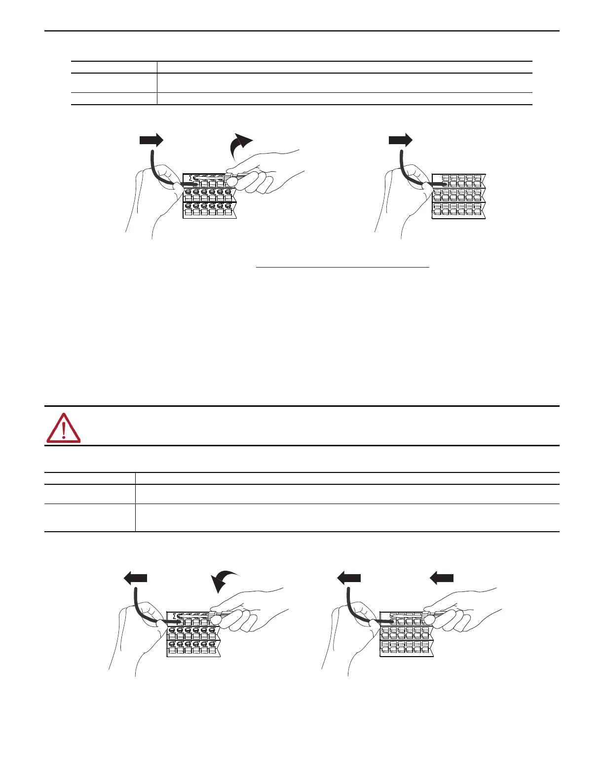
Disconnect Wires from the Terminal Base
Disconnect wires from the terminal base.
TB Type Action
Screw
1. Insert the wire into the terminal.
2. Turn the screwdriver to close the terminal on the wire. Torque the screw to 0.4 N•m (3.5 lb•in).
Spring Push the wire into the terminal. If the wire is too thin, crimp a wire ferrule on the wire and insert it.
WARNING: If you connect or disconnect wiring while power is applied, an electrical arc can occur. This could cause an explosion in hazardous location
installations. Be sure that power is removed or the area is nonhazardous before proceeding.
TB Type Action
Screw
1. Turn the screwdriver counter-clockwise to open the terminal.
2. Remove the wire.
Spring
1. Insert and hold a screwdriver in the slot above the terminal.
2. Remove the wire.
3. Pull out the screwdriver.
Spring-type TBScrew-type TB
Screw-type TB Spring-type TB

 Loading...


