Rockwell Automation Publication 5094-IN009C-EN-P - May 2022 5
FLEX 5000 High-speed Counter I/O Modules Installation Instructions
Before You Begin
Before you install the module, you must install a FLEX 5000 I/O system. At minimum, the system must include a FLEX 5000 EtherNet/IP™ adapter and backplane end cap. For more
information on how to install a FLEX 5000 I/O system, see the FLEX 5000 EtherNet/IP Adapter Installation Instructions, publication 5094-IN001, and the FLEX 5000 Terminal Base
Assembly Modules Installation Instructions, publication 5094-IN010.
You can install the module next to any FLEX 5000 I/O module.
Required Components
To install the module, you need the physical components that are listed in Table 1.
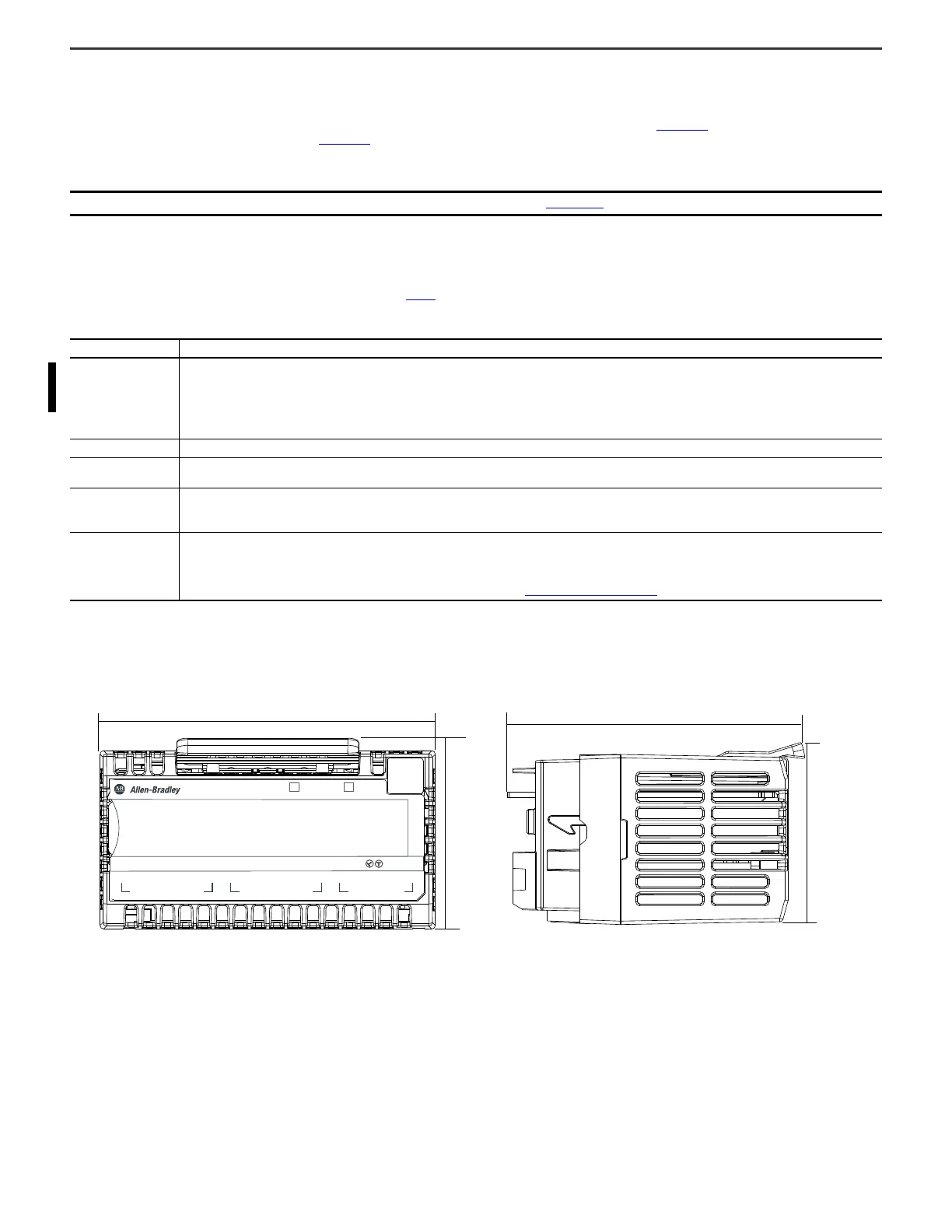
Dimensions
IMPORTANT See the FLEX 5000 High Speed Counter I/O Modules User Manual, publication 5094-UM003, for firmware and software requirements.
Table 1 - Components Needed for FLEX 5000 I/O Module Installation
Component Description
Terminal base
5094-TB3 (consists of a 5094-MB and 5094-RTB3) or
5094-TB3S (consists of a 5094-MB and 5094-RTB3S) or
5094-TB3XT (consists of a 5094-MBXT and 5094-RTB3XT) or
5094-TB3SXT (consists of a 5094-MBXT and 5094-RTB3SXT)
IMPORTANT: You must order terminal bases (TBs), or mounting bases (MBs) and removable terminal bases (RTBs) separately. TBs, MBs, and RTBs do not ship with FLEX 5000
I/O modules.
Shield bar The 5094-STB shield bar accessory is recommended with 5094-HSC and 5094-HSCXT modules. The 5094-STB shield bar accessory is available separately in a pack of five.
DIN rail
Compatible zinc-plated, yellow-chromate steel DIN rail.
You can use a steel DIN rail such as the Allen-Bradley 199-DR1; 46277-3; EN50022 – 35 x 7.5 mm (1.38 x 0.30 in.).
End cap
An end cap ships with a FLEX 5000 EtherNet/IP adapter.
You can order end caps separately:
5094-ECR-QTY5 – End cap, Pack of 5
Tools
The following tools are needed:
•Screwdriver
• Wire stripper
•Wires
For more information on available wire sizes and wire insulation stripping length, see Module Specifications
on page 13.
A
BZ
3B10AZ 2
STATUS
POWER
CH 0
CH 1
OUTPUTS
HIGH SPEED 2 COUNTER WITH DIGITAL 4 OUTPUTS
5094-HSC
4
1
TB3
FLEX 5000
®
I/O
94.0 mm (3.70 in.)
54.0 mm
(2.13 in.)
54.0 mm
(2.13 in.)
FRONT VIEW SIDE VIEW
87.0 mm (3.43 in.)

 Loading...


