Rockwell Automation Publication 5094-IN009C-EN-P - May 2022 9
FLEX 5000 High-speed Counter I/O Modules Installation Instructions
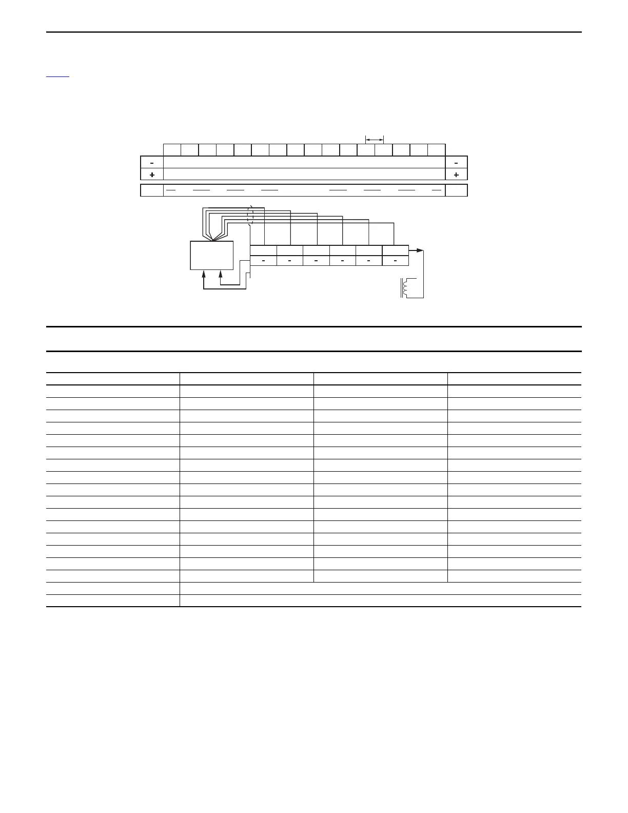
Wiring Diagrams
Figure 1 is an example wiring diagram for the 5094-HSC and 5094-HSCXT modules connected to a differential encoder. The 5094-HSC and the 5094-HSCXT modules must be used
with the 5094-STB shield bar accessory.
Figure 1 - 5094-HSC and 5094-HSCXT Wiring Diagram - Differential Encoder
IMPORTANT We recommend that you use twisted pair, individually shielded cable with a maximum length of 300 m (1000 ft) when connecting a differential encoder.
For more information on the cable type to use, see the encoder documentation.
Wiring Connections for 5094-HSC and 5049-HSCXT
Input Terminal Common Terminal Voltage Terminal
Input AO+ 0 17 35
Input A0- 1 18 36
Input B0+ 2 19 37
Input B0- 3 20 38
Input Z0+ 4 21 39
Input Z0- 5 22 40
Input A1+ 6 23 41
Input A1- 7 24 42
Input B1+ 8 25 43
Input B1- 9 26 44
Input Z1+ 10 27 45
Input Z1- 11 28 46
Output O0 12 29 47
Output O1 13 30 48
Output O2 14 31 49
Output O3 15 32 50
V DC Common 16 and 33
+V DC 34 and 51
TB3 Terminal Base with 5094-STB shield bar accessory
A0+ A0- B0+ B0- Z0+ Z0- A1+ A1- B1+ B1- Z1+ Z1- O0
3 mm
O1 O2 O3
Common
Voltage
Shield bar
A+
Solenoid
Encoder/Pulse
A- B+ B- Z+
+-
Z-

 Loading...


