10 Rockwell Automation Publication 5094-IN009C-EN-P - May 2022
FLEX 5000 High-speed Counter I/O Modules Installation Instructions
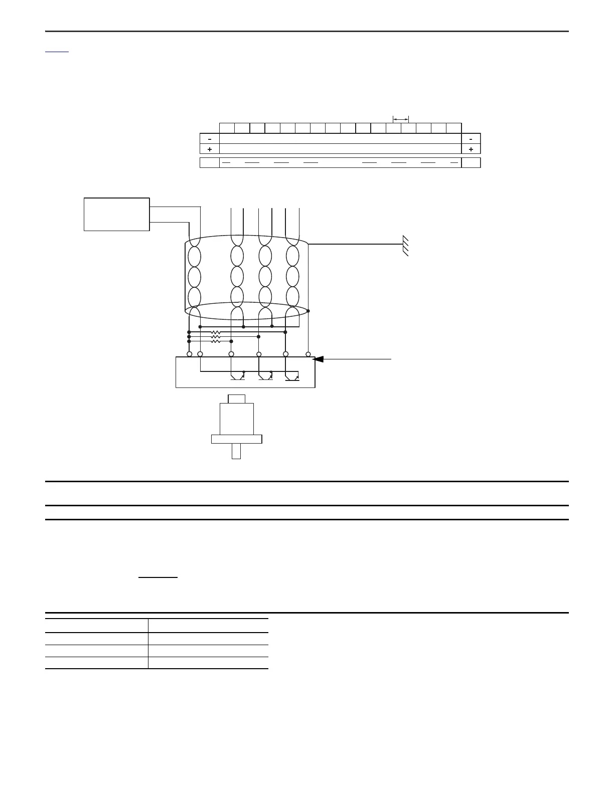
Figure 2 shows a wiring diagram for the 5094-HSC and 5094-HSCXT modules connected to a single-ended encoder. The 5094-HSC and the 5094-HSCXT modules must be used with
the 5094-STB shield bar accessory.
Figure 2 - 5094-HSC and 5094-HSCXT Wiring Diagram - Single-ended Encoder
IMPORTANT We recommend that you use twisted pair, individually shielded cable with a maximum length of 300 m (1000 ft) when connecting a single-ended
encoder. For more information on the cable type to use, see the encoder documentation.
IMPORTANT External resistors, as indicated in the R location, are required if they are not internal to the encoder. The pull-up resistor (R) value depends on the power
supply value. The following table shows the maximum resistor values for typical supply voltages. To calculate the maximum resistor value, use the
following formula:
Power Supply Voltage (V DC)
Pull-up Resistor Value (R), Max
(1)
(1) Resistance values can change, depending on your application. The minimum resistor (R)
value depends on the current sinking capability of the encoder.
5 500 Ω
12 2250 Ω
24 5250 Ω
Allen-Bradley 845H series
single-ended encoder
+V DC
Power
supply
AVS
COM
GND B Z
Shield
Shield/Housing
Connect only if the housing is
electronically isolated from the motor and
ground.
R
Input A0+
Input A0-
Input B0+
Input B0-
Input Z0+
Input Z0-
Input A1+
Input A1-
Input B1+
Input B1-
Input Z1+
Input Z1-
Output 0
Output 1
Output 2
Output 3
Earth Ground
If the module is installed on a DIN rail
that is grounded, you can connect the
cable shield to either terminal labeled
Chassis instead of the Earth Ground.
A0+ A0- B0+ B0- Z0+ Z0- A1+ A1- B1+ B1- Z1+ Z1- O0
3 mm
O1 O2 O3
Common
Voltage
Shield bar
TB3 Terminal Base with 5094-STB shield bar accessory
Shield bar accessory
VDC - Vmin
Imin
R =
Where:
R = Maximum pull-up resistor value
VDC = Power supply voltage
Vmin = 3.0V DC
Imin = 4.0 mA

 Loading...


