4 Rockwell Automation Publication 5094-IN009C-EN-P - May 2022
FLEX 5000 High-speed Counter I/O Modules Installation Instructions
Special Conditions for Safe Use
Prevent Electrostatic Discharge
Electrical Safety Considerations
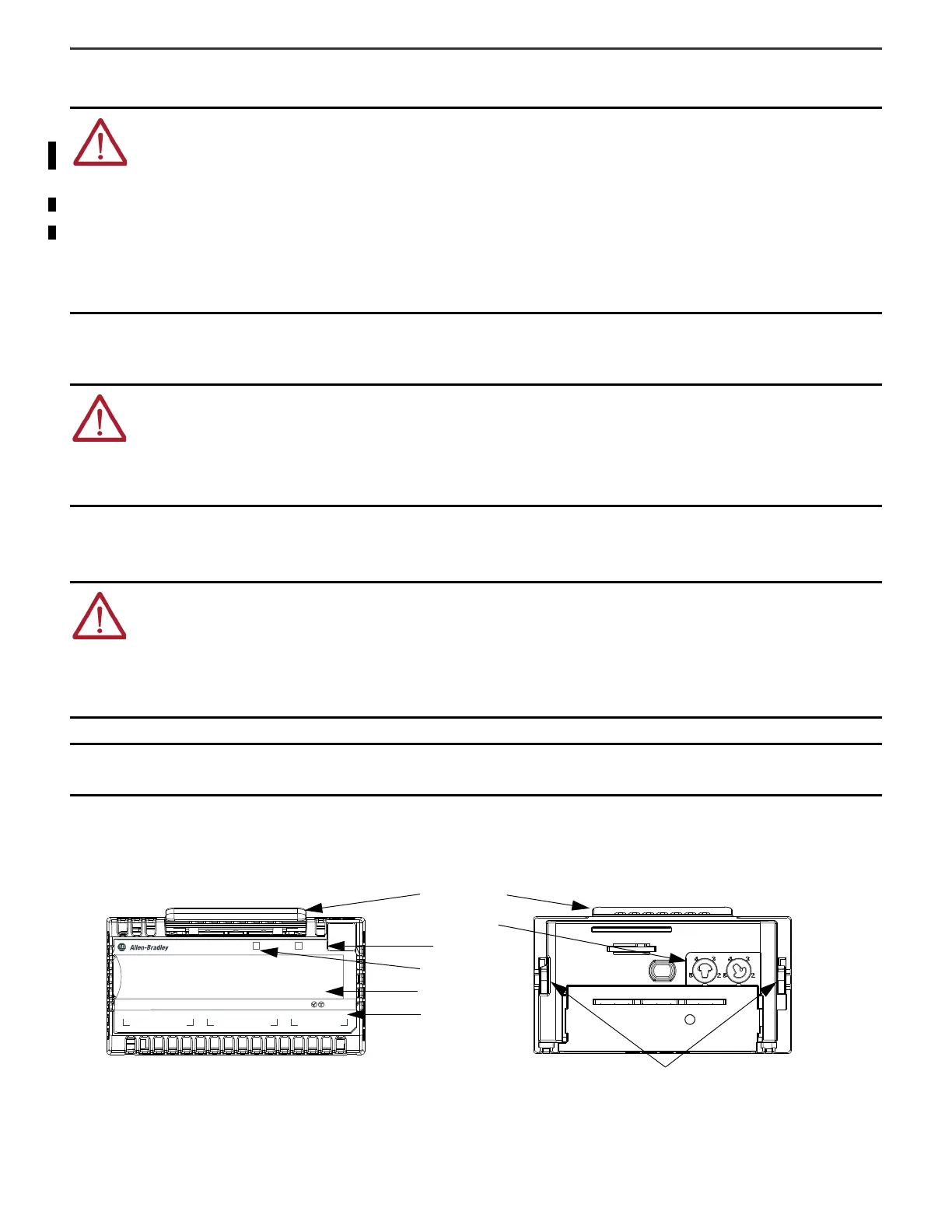
About the Module
WARNING: :
• This equipment is not resistant to sunlight or other sources of UV radiation.
• This equipment shall be mounted in an UKEX/ATEX/IECEx Zone 2 certified enclosure with a minimum ingress protection rating of at least IP54 (in accordance
with EN/IEC 60079-0) and used in an environment of not more than Pollution Degree 2 (as defined in EN/IEC 60664-1) when applied in Zone 2 environments. The
enclosure must be accessible only by the use of a tool.
• This equipment shall be used within its specified ratings defined by Rockwell Automation.
• Transient protection shall be provided that is set at a level not exceeding 140% of the peak rated voltage value at the supply terminals to the equipment.
• The instructions in the user manual shall be observed.
• This equipment must be used only with UKEX/ATEX/IECEx certified Rockwell Automation backplanes.
• Secure any external connections that mate to this equipment by using screws, sliding latches, threaded connectors, or other means provided with this product.
• Do not disconnect equipment unless power has been removed or the area is known to be nonhazardous.
• Earthing is accomplished through mounting of modules on rail.
• The installer shall ensure that the service temperature of the suitably-certified enclosure and the “maximum ambient” temperature of the module when
installed is not exceeded.
ATTENTION: This equipment is sensitive to electrostatic discharge, which can cause internal damage and affect normal operation. Follow these guidelines
when you handle this equipment:
• Touch a grounded object to discharge potential static.
• Wear an approved grounding wriststrap.
• Do not touch connectors or pins on component boards.
• Do not touch circuit components inside the equipment.
• Use a static-safe workstation, if available.
• Store the equipment in appropriate static-safe packaging when not in use.
ATTENTION:
• All wiring must comply with applicable electrical installation requirements (N.E.C. article 501-4(b)).
• Wire conductor and insulation ratings shall support minimum temperature rating of 105 °C (221 °F).
• Do not wire more than 1 conductor on any terminal.
• In case of malfunction or damage, no attempts at repair should be made. The module should be returned to the manufacturer for repair. Do not dismantle the
module.
• This equipment is certified for use only within the surrounding air temperature range of -40…+70 °C (-40…+158 °F) The equipment must not be used outside of
this range.
• Use only a soft dry anti-static cloth to wipe down equipment. Do not use any cleaning agents.
IMPORTANT Any illustrations, charts, sample programs, and layout examples shown in this publication are intended solely for the purposes of example. Since there
are many variables and requirements associated with any particular installation, Rockwell Automation does not assume responsibility or liability for
actual use based upon the examples shown in this publication.
A
BZ
3B10AZ 2
STATUS
POWER
CH 0
CH 1
OUTPUTS
HIGH SPEED 2 COUNTER WITH DIGITAL 4 OUTPUTS
5094-HSC
4
1
TB3
FLEX 5000
®
I/O
Module release lever
Latching hook
I/O status indicators
Slide-in writable label
SA power indicators
FRONT VIEW
BACK VIEW
Keyswitch ports
Module status

 Loading...


