Rockwell Automation Publication 5094-IN009C-EN-P - May 2022 13
FLEX 5000 High-speed Counter I/O Modules Installation Instructions
Replace the Module
To replace the module, follow the steps that are described beginning at Install the Module on page 6.
Module Specifications
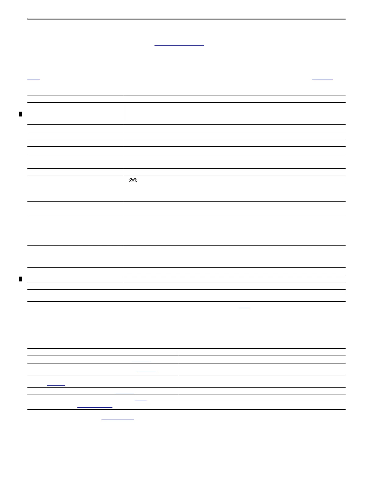
Table 2 lists a subset of the module specifications. For a complete list of specifications, see the FLEX 5000 I/O Modules Specifications Technical Data, publication 5094-TD001.
Additional Resources
For more information on the products that are described in this publication, use these resources.
You can view or download publications at rok.auto/literature
. To order paper copies of technical documentation, contact your local Allen-Bradley distributor or Rockwell Automation
sales representative.
Table 2 - 5094-HSC and 5094-HSCXT High Speed Counter Module Specifications
Attribute Value
Temperature, operating
IEC 60068-2-1 (Test Ad, Operating Cold),
IEC 60068-2-2 (Test Bd, Operating Dry Heat),
IEC 60068-2-14 (Test Nb, Operating Thermal Shock)
-40 °C ≤ Ta ≤ +70 °C (-40 °F ≤ Ta ≤ +158 °F)
Temperature, surrounding air, max 70 °C (158 °F)
Enclosure type rating None (open-style)
Input ratings (IN), per channel, max 8 mA @ 18…32V DC
Output ratings (OUT), per channel 1 A @ 18…32V DC
Output ratings (OUT), per module 3 A
Backplane Power (BP), max 67 mA @ 15V DC
Sensor Actuator Power (SA), max 3 A @ 18…32V DC
TB keying
Wiring category
(1)
(1) Use this Conductor Category information for planning conductor routing. See the Industrial Automation Wiring and Grounding Guidelines, publication 1770-4.1.
2 – on output ports
2 – on power ports
2 – on shielded counter ports
Wire size
0.34…2.5 mm
2
(22…14 AWG) solid or stranded copper wire rated at 105 °C (221 °F), or greater,
1.2 mm (3/64 in.) insulation max
Insulation stripping length
Screw-type TB:
0.34…2.5 mm
2
(22…14 AWG) =12 mm ± 1 mm (0.47 ± 0.04 in.)
Spring-type TB:
0.34…1.3 mm
2
(22…16 AWG) = 10 mm ± 1 mm (0.39 ± 0.04 in.)
2.5 mm
2
(14 AWG) = 15 mm ± 1 mm (0.59 ± 0.04 in.)
TB torque specifications
Screw-type TB:
0.4 N•m (3.5 lb•in)
Spring-type TB:
Not applicable
North American temp code T4
UKEX/ATEX temp code T4
IECEx temp code T4
Corrosion resistance classification
5094-HSC – ISA S71.04 G2
5094-HSCXT – ISA S71.04 G3
Resource Description
FLEX 5000 I/O Modules Specifications Technical Data, publication 5094-TD001
. Provides FLEX 5000 EtherNet/IP adapters and FLEX 5000 I/O module specifications.
FLEX 5000 High Speed Counter I/O Modules User Manual, publication 5094-UM003
.
Describes how to install, configure, and operate the FLEX 5000 high-speed counter
I/O modules.
FLEX 5000 Terminal Base Assembly Modules Installation Instructions,
publication 5094-IN010
.
Provides information on how to install FLEX 5000 terminal base assemblies and accessories.
FLEX 5000 Shield Bar Product Information, publication 5094-PC002
. Provides specifications for the shield bar and jumper accessories.
Industrial Automation Wiring and Grounding Guidelines, publication 1770-4.1
. Provides general guidelines for installing a Rockwell Automation industrial system.
Product Certifications website, rok.auto/certifications
. Provides declarations of conformity, certificates, and other certification details.

 Loading...


