Rockwell Automation Publication 440G-UM001C-EN-P - June 2019 49
Application Examples Chapter 7
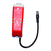
As an alternative, the user can use an 871A-TS8-D1 field attachable connector
at the 440G-LZ and a 5-wire cordset (889D-M5NC-x)
Figure 24 - ArmorBlock Schematic
Figure 25 shows the General Tab of the ArmorBlock Module Properties. The
Input Status must be set to “Combined Status – Muting” and the Output Data
must be set to “Combined.”
Figure 25 - Module Properties — General
Power
AE
BF
DH
CG
EtherNet
4
3
2
1
1
2
3
4
1 T1
2 I1
3 C
4 I0
5 T0
1 T1
2 I1
3 C
4 I0
5 T0
1 T1
2 I1
3 C
4 I0
5 T0
1 T1
2 I1
3 C
4 I0
5 T0
1 T1
2 I1
3 C
4 I0
5 T0
1 T1
2 I1
3 C
4 I0
5 T0
X100 X1X10
2 O1
1+24
3 C
4 O0
5 C
2 O1
1+24
3 C
4 O0
5 C
3
5
4
21
3
5
4
21
+24V DC
24V Com
871A-TS5-DM1 5 pin
Field Attachable Connector
1732ES-IB12XOB4
Red (OSSD A+)
Pink (OSSD B)
Green (Lock)
White (Aux)
Blue (Gnd)
Grey (OSSD A)
Yellow (OSSD B+)
Brown (+24)
889D-F8NB-5
N/C
K1
Brown (1) White(2)
Black (4)
Grey(5)
K2
889D-E5NC-10
100S or 700S or 700-HPS
Contactors and Relays
K2
889D-E5NC-10
White (2) A1 A2 Blue (3)
Black(4) A1 A2 (Grey(5)
K1
Safety
Gate
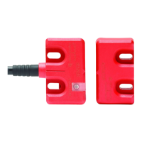
440G-LZS21SPRH
Power-To-Release
Aux = Lock Status
Diag
Status
440G-LZ
 Loading...