114 Rockwell Automation Publication 750-RM100A-EN-P - August 2019
Chapter 11 Application References
• The drive is equipped with an I/O card, such as a 20-750-2262C-2R, in
port (slot) 4. Mechanical brake control is wired to Output Relay 0 on that
card.
Configure the Modular Control Profiles
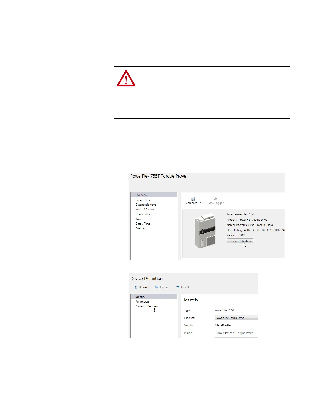
1. Power up the drive and establish a connection with Connected
Components Workbench software.
2. Navigate to the Overview page for the drive. Then click Device
Definition.
3. Then click Dynamic Features.
ATTENTION: Loss of control in suspended load applications can cause personal
injury and/or equipment damage. The drive or a mechanical brake must always
control the loads. Parameters 9:60 [Brk Release Time]…78 [DI FloatMicroPsn]
are designed for lifting/torque prove applications. It is the responsibility of the
engineer and/or end user to configure drive parameters, test any lifting
functionality and meet safety requirements in accordance with all applicable
codes and standards.

 Loading...


